
Wireless positioning calibration system and wireless positioning calibration method

a wireless positioning and calibration system technology, applied in the direction of direction finders using radio waves, instruments, transmission monitoring, etc., can solve the problems of lowering the accuracy of positioning using csi, increasing error rate, and unable to provide an improved indoor positioning method based on existing base stations to maximize positioning accuracy

Active Publication Date: 2020-03-12
IND TECH RES INST
View PDF0 Cites 9 Cited by
  • Summary
  • Abstract
  • Description
  • Claims
  • Application Information

AI Technical Summary

Benefits of technology

This patent is about a new technology that helps improve the efficiency of electrical power distribution systems. The technology involves using special materials called nanoparticles that can be added to the electrical insulation material of the system. This helps to reduce the amount of electricity that is lost during the distribution process, which can save money and improve the overall performance of the system.

Problems solved by technology

However, channel state information are processed by the antenna hardware circuits, and the hardware circuit of each antenna may create additional phase variations, which leads to errors in the positioning of a mobile device relative to the base station, lowering the accuracy of positioning using CSI.
In other words, if the spacing between the antennas in the base station are altered, the error rate increases, and re-measuring of the spacing between the antennas becomes necessary.
With this in mind, how to provide an improved indoor positioning method based on existing base stations to maximize the accuracy of positioning remains a problem to be solved.

Method used


Image

  • Wireless positioning calibration system and wireless positioning calibration method
  • Wireless positioning calibration system and wireless positioning calibration method
  • Wireless positioning calibration system and wireless positioning calibration method

Examples


Embodiment Construction

[0021]In the following detailed description, for purposes of explanation, numerous specific details are set forth in order to provide a thorough understanding of the disclosed embodiments. It will be apparent, however, that one or more embodiments may be practiced without these specific details. In other instances, well-known structures and devices are schematically shown in order to simplify the drawing.

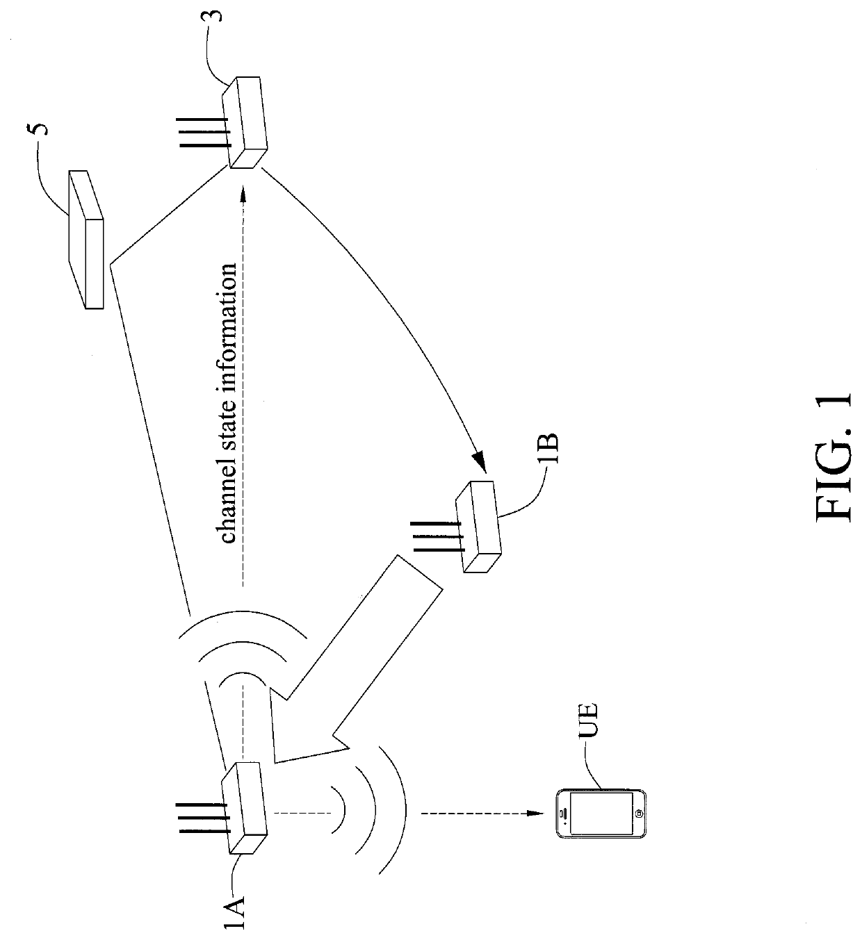
[0022]A wireless positioning calibration system and a wireless positioning calibration method are disclosed. With channel state information (CSI) and a sniffer capability of the base station, the positioning errors caused by antenna hardware circuits and antenna spacing errors can be compensated to effectively improve the accuracy in positioning.

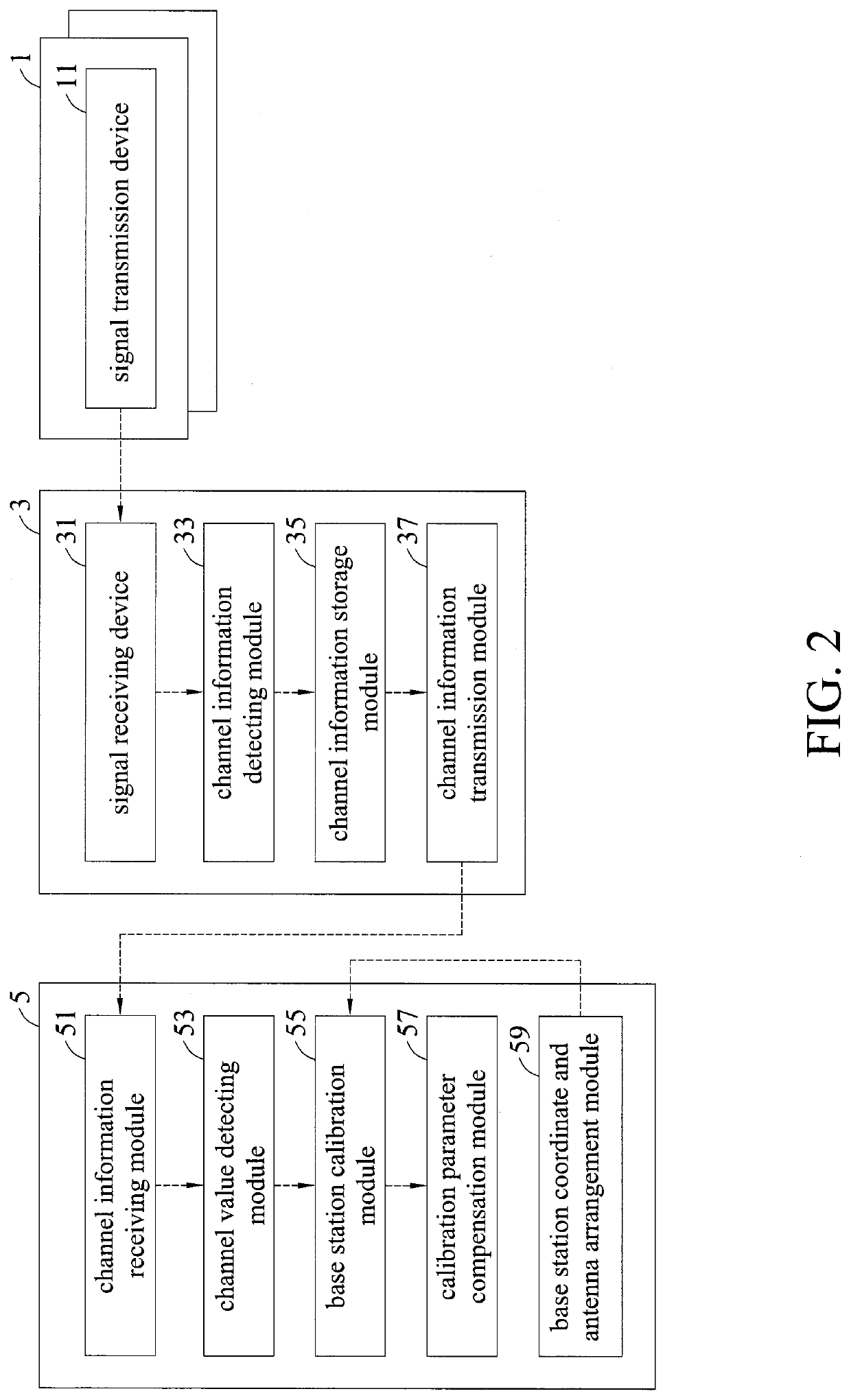
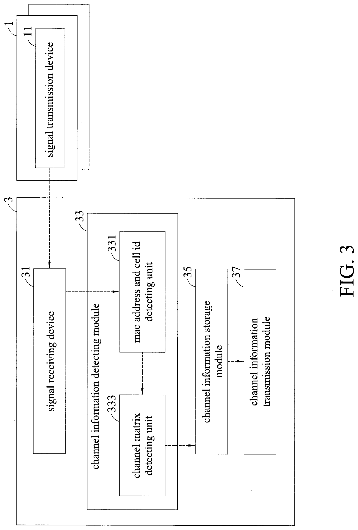
[0023]FIG. 1 is a wireless positioning calibration system in accordance with the present disclosure. The wireless positioning calibration system includes a plurality of transmission base stations 1, at least one sniffer base station 3 and a ...


PUM


Abstract

Provided is a wireless positioning calibration system, including a plurality of transmission base stations, at least one sniffer base station and a positioning server. The at least one sniffer base station receives a plurality of channel state information (CSI) transmitted by the plurality of transmission base stations. The positioning server receives the plurality of CSI transmitted by the at least one sniffer base station. The positioning server calculates a phase error and an antenna spacing error generated by the at least one sniffer base station by means of the plurality of CSI, and compensates the phase error and the antenna spacing error. A wireless positioning calibration method is also provided.

Description

CROSS-REFERENCE TO RELATED APPLICATIONS[0001]This application claims priority to Taiwanese Application Serial No. 107131639, filed on Sep. 7, 2018. The entirety of the above-mentioned patent application is hereby incorporated by reference herein and made a part of this specification.BACKGROUND1. Technical Field[0002]The present disclosure generally relates to wireless positioning systems and, more specifically, to a wireless positioning calibration system and a wireless positioning calibration method that use channel state information (CSI).2. Description of Related Art[0003]With the continuous advances in the communication technology, accurate indoor positioning services are required in a myriad of applications to satisfy the needs of users. Indoor positioning applications create a lot of business opportunities in the enterprise context, including visitor management, personnel management, area control, emergency call etc., and are thus of imminent importance. In addition, Next Gene...

Claims


Application Information

Patent Timeline
Patent Type & Authority Applications(United States)
IPC IPC(8): H04B17/12H04B7/06H04B7/08H04B17/318H04W64/00
CPCH04B7/0626H04W64/003H04B7/086H04B17/318H04W24/10H04B17/12H04B17/309G01S3/023G01S3/46G01S5/021G01S5/04G01S5/12H04W88/085H04W92/20
Inventor CHUI, PI-CHENHO, TING-WULIU, CHIA-LUNG
Owner IND TECH RES INST
Learn More