Weightlifting Machine

a weight-lifting machine and weight-lifting technology, applied in the field of weight-lifting machines, can solve the problems of occupying valuable space on the gym floor, significant financial expenditure, and affecting the performance of the machine, and achieve the effect of raising the weight suppor

Active Publication Date: 2020-04-16
COULTER VENTURES
View PDF0 Cites 26 Cited by
  • Summary
  • Abstract
  • Description
  • Claims
  • Application Information

AI Technical Summary

Benefits of technology

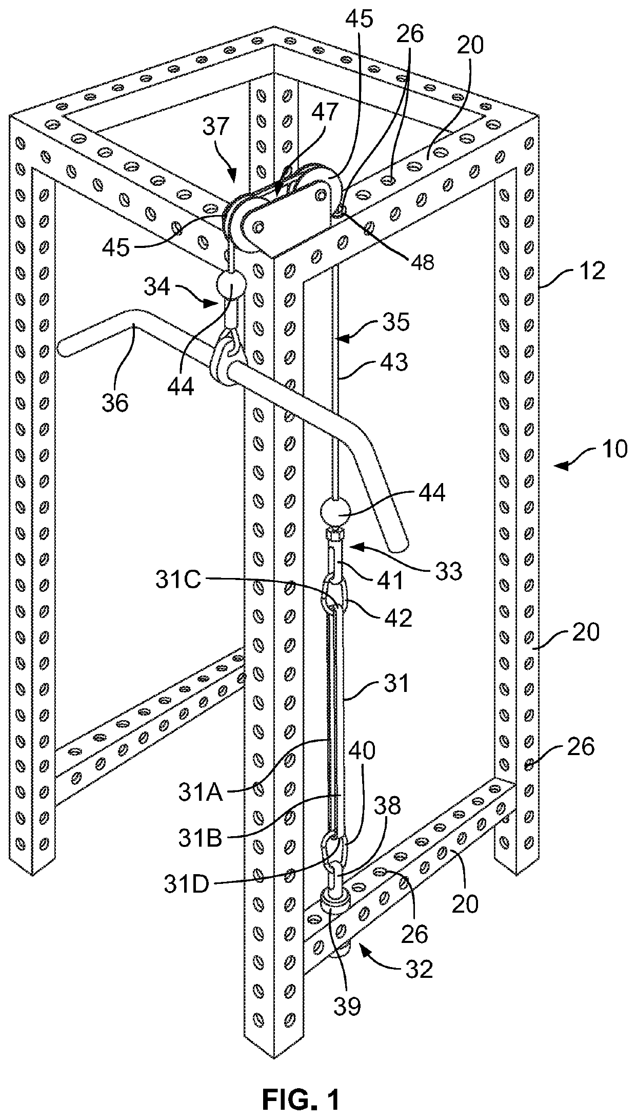
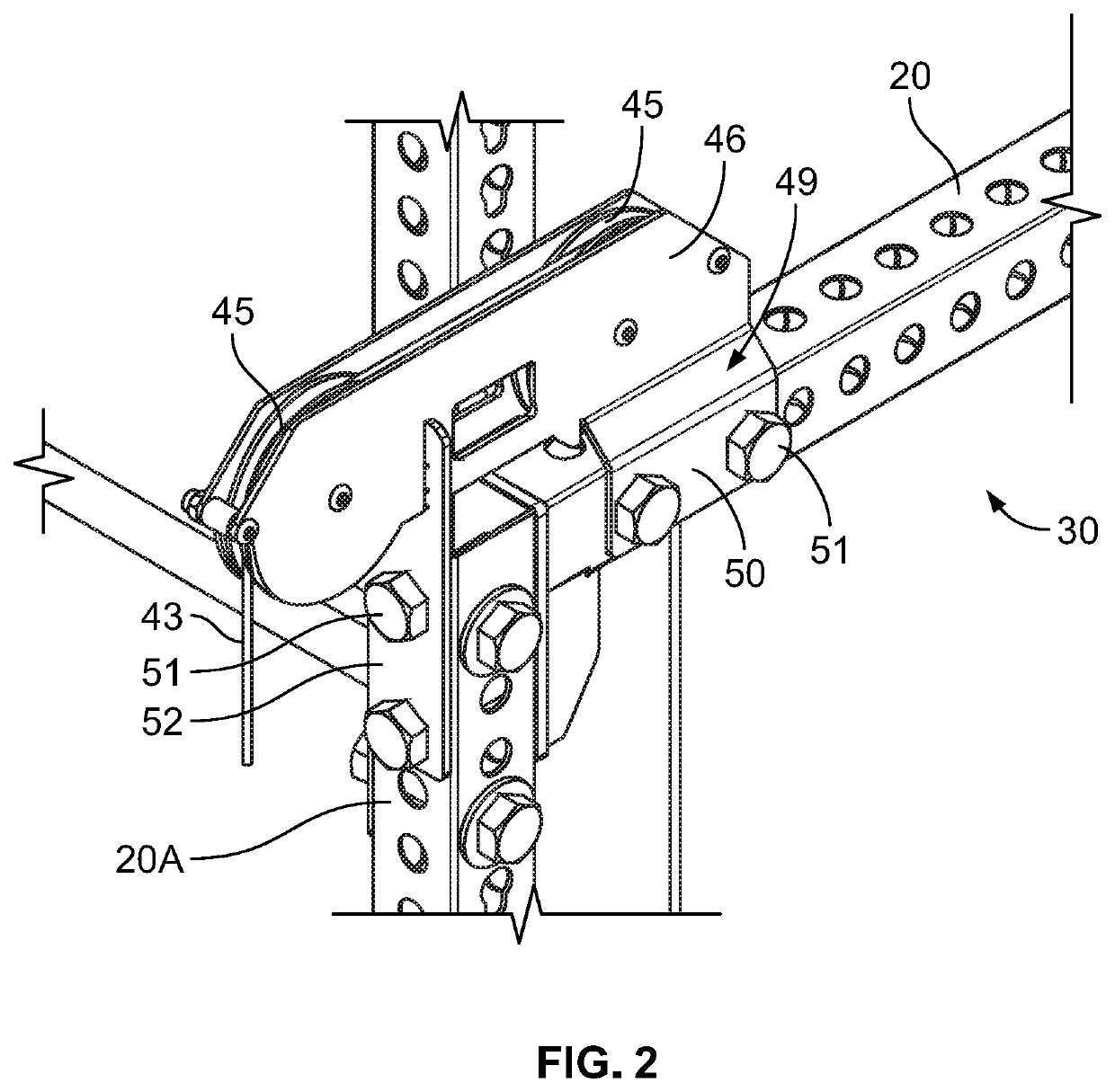
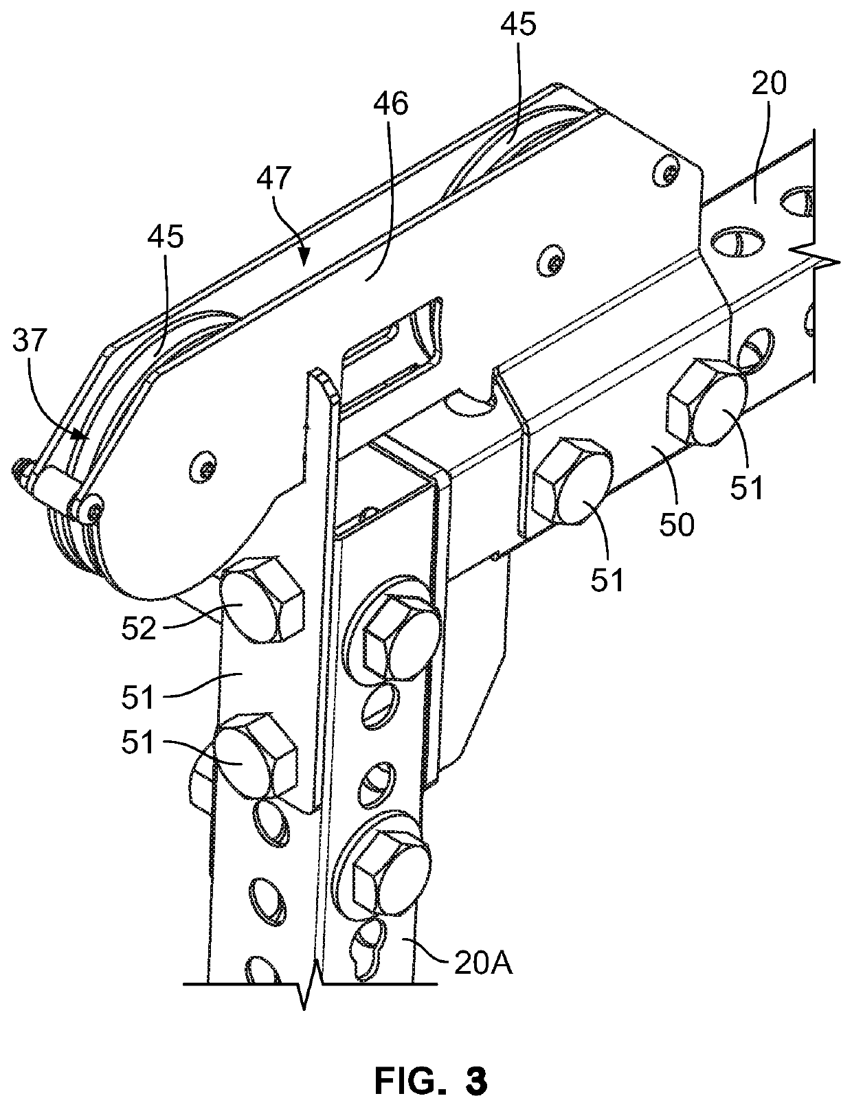
[0006]Additional aspects of this disclosure may relate to a method of arranging a weight rack assembly, including: providing a frame having a plurality of vertical frame members and a plurality of lateral frame members, where the lateral frame members connect to the vertical frame members, and each lateral frame member and each vertical frame member may include a rectangular metal tube having four side surfaces defining a hollow interior with a plurality of holes on at least one of the side surfaces of each lateral and vertical frame member. The method may also include mounting a pulley assembly to the frame, where the pulley assembly includes a first pulley connected to the frame at a first location and a second pulley connected to a first lateral frame member of the plurality of lateral frame members at a second location such that the second pulley is spaced from the first pulley. In addition, the method includes connecting a cable with the pulley assembly, where the cable is configured for engaging a resistance element and the cable extends from a grip attachment at a first end of the cable and engages the first pulley to redirect the cable and the cable further extends from the first pulley to the second pulley and engages the second pulley to redirect the cable. The cable may extend through a first hole of the plurality of holes located in an upper surface of the first lateral frame member, through the hollow interior of the first lateral frame member, and through a second hole of the plurality of holes on a lower surface of the first lateral frame member. The method may also include securing a first protector in the first hole in the upper surface of the first lateral frame member, where the cable extends through an aperture of the first protector, and securing a second protector in the second hole in the lower surface of the first lateral frame member, where the cable extends through an aperture of the second protector. The method may further include: connecting a second end of the cable to a movable connection; connecting a first end of a resistance band to a fixed connection attached to a second lateral frame member, where the second lateral frame member is spaced apart from the first lateral frame member; and connecting a second end of a resistance band to the movable connection such that the movable connection stretches the resistance band when the grip attachment is moved in a direction away from the first pulley.
[0007]Yet other aspects of this disclosure may relate to a weight rack system including a frame having an arrangement of a plurality of vertical frame members that are connected together with a plurality of lateral frame members extending between the plurality of vertical frame members, where each lateral frame member includes a rectangular metal tube having fours side surfaces defining a hollow interior with a plurality of holes on at least one of the side surfaces of each frame lateral and vertical member, a pulley assembly attached to the frame, where the pulley assembly includes a first pulley and a mount connected to the frame, wherein the first pulley is rotatably mounted on the mount. The rack may further include a cable connected at a first end to a movable connection and connected at a second end to a grip attachment, where the cable extends from the grip attachment to the first pulley and engages the first pulley to redirect the cable, and the cable further extends from the first pulley to the movable connection. A resistance band may be attached to the movable connection, where the resistance band is further attached to a fixed connection connected to the frame and spaced apart from the moveable connection, such that resistance band extends between the moveable connection and the fixed connection in tension. The movable connection may be configured to move away from the fixed connection to stretch the resistance band when the grip attachment is moved in a direction away from the first pulley, via the cable. The weight rack may further include a sheath completely encircling at least a portion of a length of the resistance band, where the sheath includes a flexible tubular body with an internal passage receiving the resistance band therein, and where the tubular body is connected to the fixed connection and to the movable connection such that the sheath is configured to extend when the movable connection is moved away from the fixed connection. The sheath may encircle an entire length of the resistance band. The tubular body includes a first connecting structure on a first end of the tubular body directly connected to the fixed connection and a second connecting structure on a second end of the tubular body directly connected to the movable connection. The first and second connecting structures may be loops that are attached to the first and second ends of the tubular body. The sheath may be formed from a nylon-based fabric.
[0008]Still further aspects of the disclosure may relate to a weight rack system, including a frame including an arrangement of a plurality of vertical frame members that are connected together with a plurality of lateral frame members extending between the plurality of vertical frame members, and a pulley assembly attached to the frame, where the pulley assembly includes a first pulley and a mount connected to the frame, and where the first pulley is rotatably mounted on the mount. The rack system may include a cable connected at a first end to a movable connection and at a second end to a grip attachment, where the cable extends from the grip attachment to the first pulley and engages the first pulley to redirect the cable. The cable may further extend from the first pulley to the movable connection. The rack may further include a weight support attached to the movable connection, where the weight support includes a support plate with a shaft extending upward from the support plate, wherein the weight support is configured to support one or more weight plates such that the one or more weight plates rest on the support plate, and the shaft is configured to extend through a hole in each of the one or more weight plates. The movable connection may be configured to raise the weight support when the grip attachment is moved in a direction away from the first pulley, via the cable. The weight rack may further include a resistance band, where the weight support further has a connection beneath the support plate, and where the resistance band is attached to the connection and to a fixed connection attached to the frame. The resistance band may extend between the connection beneath the support plate and the fixed connection in tension, and where the resistance band is configured to be stretched when the weight support is raised via movement of the grip attachment. A base support may be attached to a first vertical frame member of the plurality of vertical frame members, where the base support includes a mounting structure configured to releasably attach to the first vertical frame member and a support member configured to engage and support the weight support at an elevated position. The support member of the base support may extend into a movement path of the weight support defined by a range of motion of the cable, such that the support member of the base support is configured to engage and support the weight support at the elevated position within the movement path of the weight support. The support member may include two legs extending from a base portion thereby creating a space between the two legs, where the two legs extend away from each other. The resistance band attached to the weight support and the frame extends between the weight support and the frame, and where the resistance band extends between the space between the two legs. The mounting structure of the base support may further include a bridge member connected to the two legs, where each leg has a height that tapers from a first end proximate the base portion and a second proximate a distal end.
[0009]Other aspects of this disclosure may relate to a weightlifting assembly including: a weight rack that includes a first vertical frame member, a second vertical frame member spaced from the first vertical frame member, a first lateral frame member connected to the first vertical frame member at a first location and connected to the second vertical frame member at a second location, where the first lateral frame member includes a plurality of holes arranged along a top surface and a bottom surface, and a second lateral frame member connected to the first vertical frame member and connected to the second vertical frame member, where the second lateral frame member is spaced apart from and below the first lateral frame member. The weightlifting assembly may further include a pulley assembly attached to the weight rack, where the pulley assembly includes a first pulley and a mount connected to the frame, where the first pulley is rotatably mounted on the mount. A cable may have a first end connected to a grip attachment and a second end opposite the first end, where the cable extends from the grip attachment to the first pulley and engages the first pulley to redirect the cable. A weight plate assembly may be releasably connected to the weight rack, where the weight plate assembly includes a top mount releasably connected to the first lateral frame member, where the top mount includes an opening and the cable extends through the opening, a bottom mount releasably connected to the second lateral frame member, and a plurality of weights arranged in a stack between the top mount and the bottom mount and also between the first vertical frame member and the second vertical frame member. Each weight of the plurality of weights may have a first aperture that is aligned with the opening of the top mount and a second aperture that is offset from the first aperture. The weight plate assembly may also include a first guide fixedly connected to the top mount and the bottom mount and extending vertically and linearly from the top mount to the bottom mount, where the first guide extends through the second aperture of each weight of the plurality of weights, a weight engaging member connected to the cable, where the weight engaging member is an elongated member that extends through the first aperture of each weight, and a removable pin that engages a first weight of the plurality of weights and also engages the weight engaging member such that lifting the weight engaging member is configured to lift the first weight and any additional weights of the plurality of weights stacked on top of the first weight. A first hole of the plurality of holes in the first lateral frame member may be aligned with the opening of the top mount, where the cable extends through the first hole and the opening. A first protector may be secured in the first hole of the plurality of holes in the first lateral frame member, and a second protector may be secured in a second hole on a bottom surface of the plurality of holes in the first lateral frame member, where the first hole and the second hole are aligned with each other and with the opening of the top mount. The first lateral frame member of the frame may have a hollow interior, and the first hole may be positioned on a top surface of the first lateral frame member. The cable may extend through an aperture in the first protector, extends across the hollow interior of the first lateral frame member, and extends through a second aperture in the second protector. The weight plate assembly may also include a second guide fixedly connected to the top mount and the bottom mount and extending vertically and linearly from the top mount to the bottom mount, wherein the second guide extends through a third aperture in each weight of the plurality of weights, wherein the third aperture is spaced from the second aperture.
[0010]Still other aspects of this disclosure may relate to a method of modifying a weight rack that includes providing the weight rack in a configuration for performing a first weightlifting exercise, where the weight rack includes a plurality of interconnected frame members. Each frame member may be a rectangular metal tube having four side surfaces defining a hollow interior with a plurality of holes arranged along at least a portion of a length of each frame member on at least two of the side surfaces thereof. The plurality of frame members may include a first vertical frame member, a second vertical frame member spaced from the first vertical frame member, a first lateral frame member connected to the first vertical frame member at a first location and connected to the second vertical frame member at a second location, where the first lateral frame member includes the plurality of holes arranged along at least a top surface and a bottom surface, and a second lateral frame member connected to the first vertical frame member and connected to the second vertical frame member, where the second lateral frame member is spaced apart from and below the first lateral frame member. The method may also include attaching a pulley assembly to the weight rack, where the pulley assembly comprises a first pulley and a mount connected to the frame and where the first pulley is rotatably mounted on the mount, and connecting a weight plate assembly to the weight rack, where the weight plate assembly includes a top mount releasably connected to the first lateral frame member, where the top mount includes an opening and a bottom mount releasably connected to the second lateral frame member. The weight rack may also include a plurality of weights arranged in a stack between the top mount and the bottom mount and also between the first vertical frame member and the second vertical frame member, where each weight of the plurality of weights has a first aperture that is aligned with the opening of the top mount and a second aperture that is offset from the first aperture, a first guide fixedly connected to the top mount and the bottom mount and extending vertically and linearly from the top mount to the bottom mount, where the first guide extends through the second aperture of each weight of the plurality of weights, a weight-engaging member comprising an elongated member that extends through the first aperture of each weight, and a removable pin that engages a first weight of the plurality of weights and also engages the weight-engaging member such that lifting the weight-engaging member is configured to lift the first weight and any additional weights of the plurality of weights stacked on top of the first weight. The method may further include routing a cable system through the pulley assembly such that the cable system engages the first pulley to redirect the cable system, and the cable system further extends through two holes of the plurality of holes in the first lateral frame member and through the opening of the top mount, connecting a first end of a cable system to a grip, such that the cable system extends from the grip to the first pulley, and connecting a second end of the cable system to the weight engaging member. As another option, the method may include securing a protector into the two holes of the plurality of holes prior to routing the cable system through the two holes. The weight rack may be configured for performing a second weightlifting exercise that is different from the first weightlifting exercise, such that the second weightlifting exercise is performed by pulling on the grip to raise the weight-engaging member, the first weight, and any additional weights stacked on top of the first weight, via movement of the cable system.
[0011]Yet other aspects of this disclosure may relate to a weight rack assembly including a frame including a plurality of interconnected vertical frame members and lateral frame members, a pulley assembly connected to the frame, where the pulley assembly includes a first pulley and mount rotatably supporting the first pulley, and where the pulley assembly is attached to the frame by attaching the mount to the frame. The weight rack assembly may have a cable engaged with the pulley assembly, where the cable engages the first pulley to redirect the cable, where a first end of the cable is attached to a weight support. The weight support may include a support plate with a shaft extending upward from the support plate, where the weight support is configured to support one or more weight plates such that the one or more weight plates rest on the support plate and the shaft is configured to extend through a hole in each of the one or more weight plates. Other aspects of the weight rack assembly may include a second end of the cable may be connected to a grip attachment, a base support attached to a first vertical frame member of the vertical frame members, where the base support is configured to hold the weight support, a first end of a resistance band connected to the weight support, and a second end of the resistance band connected to the frame at a location spaced from the weight support, such that the resistance band extends between the weight support and the frame in tension. The base support may include a mounting structure that is releasably attached to the first vertical frame member and a support member configured to engage and support the weight support at an elevated position, where the support member of the base support extends into a movement path of the weight support defined by a range of motion of the cable, such that the support member of the base support is configured to engage and support the weight support at the elevated position within the movement path of the weight support. The support plate may include a lower connection on a bottom surface that attaches to the first end of the resistance band. The base support may also include a mounting structure configured to releasably attach to the first vertical frame member and a support member configured to engage and support the weight support at the elevated position. The support member includes two legs extending from a base portion thereby creating a space between the two legs, where the resistance band extends between the space between the two legs. The cable may extend through a hole located in an upper surface of the first lateral frame member, and a first protector may be secured in the hole in the upper surface of the first lateral frame member, wherein the cable extends through an aperture of the first protector.

Problems solved by technology

These types of weightlifting machines may often be limited so a user can only perform a limited number of exercises with them, yet these machines may take up valuable space on a gym floor.
This is a significant concern for small gyms and in-home gyms, where space may be extremely limited.
Additionally, a cable-based weightlifting machine that is configured either as a stand-alone machine or a component to be connected to a weight rack requires significant financial expenditure and may present difficulties with shipping and assembly.

Method used


Image

  • Weightlifting Machine
  • Weightlifting Machine
  • Weightlifting Machine

Examples


Embodiment Construction

[0078]While this invention is susceptible of embodiments in many different forms, there are shown in the drawings and will herein be described in detail example embodiments of the invention with the understanding that the present disclosure is to be considered as an exemplification of the principles of the invention and is not intended to limit the broad aspect of the invention to the embodiments illustrated. In the following description of various example structures according to the invention, reference is made to the accompanying drawings, which form a part hereof, and in which are shown by way of illustration various example devices, systems, and environments in which aspects of the invention may be practiced. It is to be understood that other specific arrangements of parts, example devices, systems, and environments may be utilized and structural and functional modifications may be made without departing from the scope of the present invention.

[0079]Also, while the terms “top,”“...


PUM


Abstract

A weightlifting machine that includes a pulley system and a cable system that attaches to a weight rack frame to allow a user to perform a weightlifting exercise. The pulley system may include a first pulley and a second pulley where the cable system engages each pulley. The cable system may have a first end connected to a grip attachment and a second end attached to a resistance element. The resistance element may include a resistance band, a weight support that holds a weight plate, a set of weight plates, or other type of resistance element. The cable system may extend from the pulley through an opening located one of the frame members that form the frame.

Description

CROSS-REFERENCE TO RELATED APPLICATIONS[0001]This application claims priority to U.S. Provisional Application No. 62 / 745,127 filed on Oct. 12, 2018; U.S. Provisional Application No. 62 / 745,838 filed on Oct. 15, 2018; U.S. Provisional Application No. 62 / 746,909 filed on Oct. 17, 2018; U.S. Provisional Application No. 62 / 747,953 filed on Oct. 19, 2018; U.S. Provisional Application No. 62 / 749,972 filed on Oct. 24, 2018; U.S. Provisional Application No. 62 / 750,690, filed on Oct. 25, 2018; U.S. Provisional Application No. 62 / 790,324 filed on Jan. 9, 2019; U.S. Provisional Application No. 62 / 797,048 filed on Jan. 25, 2019; and U.S. Provisional Application No. 62 / 890,419 filed on Aug. 22, 2019; all of which above referenced applications are incorporated by reference in their entireties.TECHNICAL FIELD[0002]This disclosure relates to weightlifting machines for use with weight rack assemblies, and more specifically, to weightlifting machines including components and features configured for c...

Claims


Application Information

Patent Timeline
Patent Type & Authority Applications(United States)
IPC IPC(8): A63B21/00A63B21/04A63B21/055A63B21/062A63B21/08
CPCA63B21/0428A63B21/0552A63B21/156A63B21/08A63B21/0628A63B21/062A63B2225/10A63B21/00065A63B21/154A63B21/16A63B21/4043A63B21/0442A63B21/4035A63B2071/009A63B2225/093
Inventor HENNIGER, WILLIAMDUNAHAY, NASHCOUGHLAN, LAURIE ANNMCCLURE, TYLER
Owner COULTER VENTURES
Why Eureka
Try Eureka