

Systems and methods for a suction cup device holder
- Summary
- Abstract
- Description
- Claims
- Application Information
AI Technical Summary
Benefits of technology
Problems solved by technology
Method used
Image

Examples
Embodiment Construction
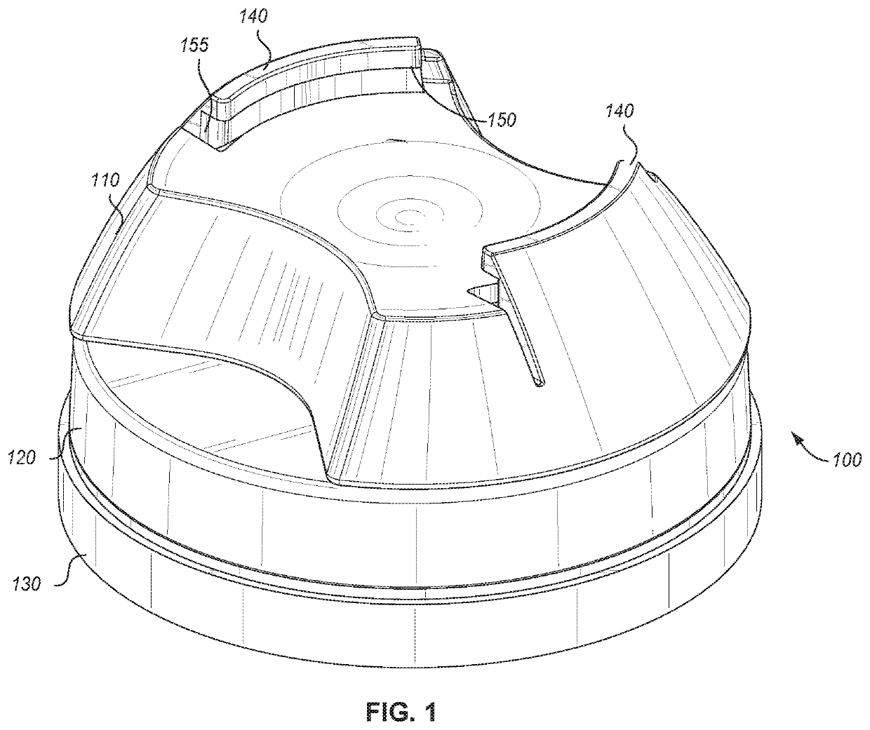
[0017]Certain terminology is used herein for convenience only and is not to be taken as a limitation on the embodiments of the systems and methods for a suction cup device holder. Essentially in many embodiments, the suction cup holder includes a suction cup that is actuated by turning a contoured tensioning device, that pulls on the suction cup, causing it to stick. Additionally, the contoured tensioning device includes a curved receiver for receiving a disk that may be attached to the back of a device. The receiver is located on the tensioning device portion of the holder. The receiver includes a lip for receiving and retaining a disk. The curved receiver is essentially shaped to receive a disk that is slightly raised off of the back of a device (such as a phone). In many embodiment, this is a portion of a circle, such that opening of the circle is greater than the diameter of the disk to be received.
[0018]FIG. 1 shows one embodiment of a suction cup device holder 100. In this emb...
PUM
 Abstract
Description
Claims
Application Information