
Alignment of magnetic materials during powder deposition or spreading in additive manufacturing

a technology of magnetic materials and additive manufacturing, applied in the direction of magnetic core manufacturing, inorganic material magnetism, application of conductive/insulating/magnetic materials on magnetic films, etc., can solve the problems of no technique, random orientation of bulk parts, etc., and achieve the effect of increasing density and stability

Inactive Publication Date: 2020-04-16
UNIVERSITY OF PITTSBURGH
View PDF0 Cites 1 Cited by
  • Summary
  • Abstract
  • Description
  • Claims
  • Application Information

AI Technical Summary

Benefits of technology

This patent describes a method for making magnetic materials or items using 3D printing. The method involves creating a temporary shape using a binder material and then removing the binder material to create a final shape with increased density and stability. The technical effect of this method is that it allows for the creation of stronger and more stable magnetic materials or items using 3D printing.

Problems solved by technology

For certain magnetic materials, a random orientation in bulk parts is not desirable.
Currently, there is no technique, especially in powder bed binder jet printing, that would allow for the microstructural or magnetic moment alignment of powder particles within a bulk metal part.

Method used


Image

  • Alignment of magnetic materials during powder deposition or spreading in additive manufacturing
  • Alignment of magnetic materials during powder deposition or spreading in additive manufacturing
  • Alignment of magnetic materials during powder deposition or spreading in additive manufacturing

Examples


example 5

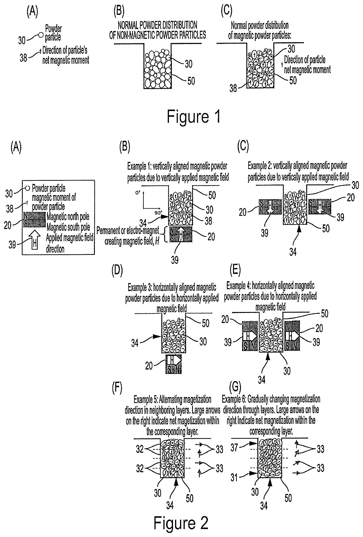
[0075 of FIG. 2(F) demonstrates a build or sample 34 that contains alternating vertical and horizontal net magnetization directions 33 between neighboring layers 32. Example 6 of FIG. 2(G) demonstrates a build 34 within which the net magnetization direction 33 gradually changes from bottom layer 31 to top layer 37.

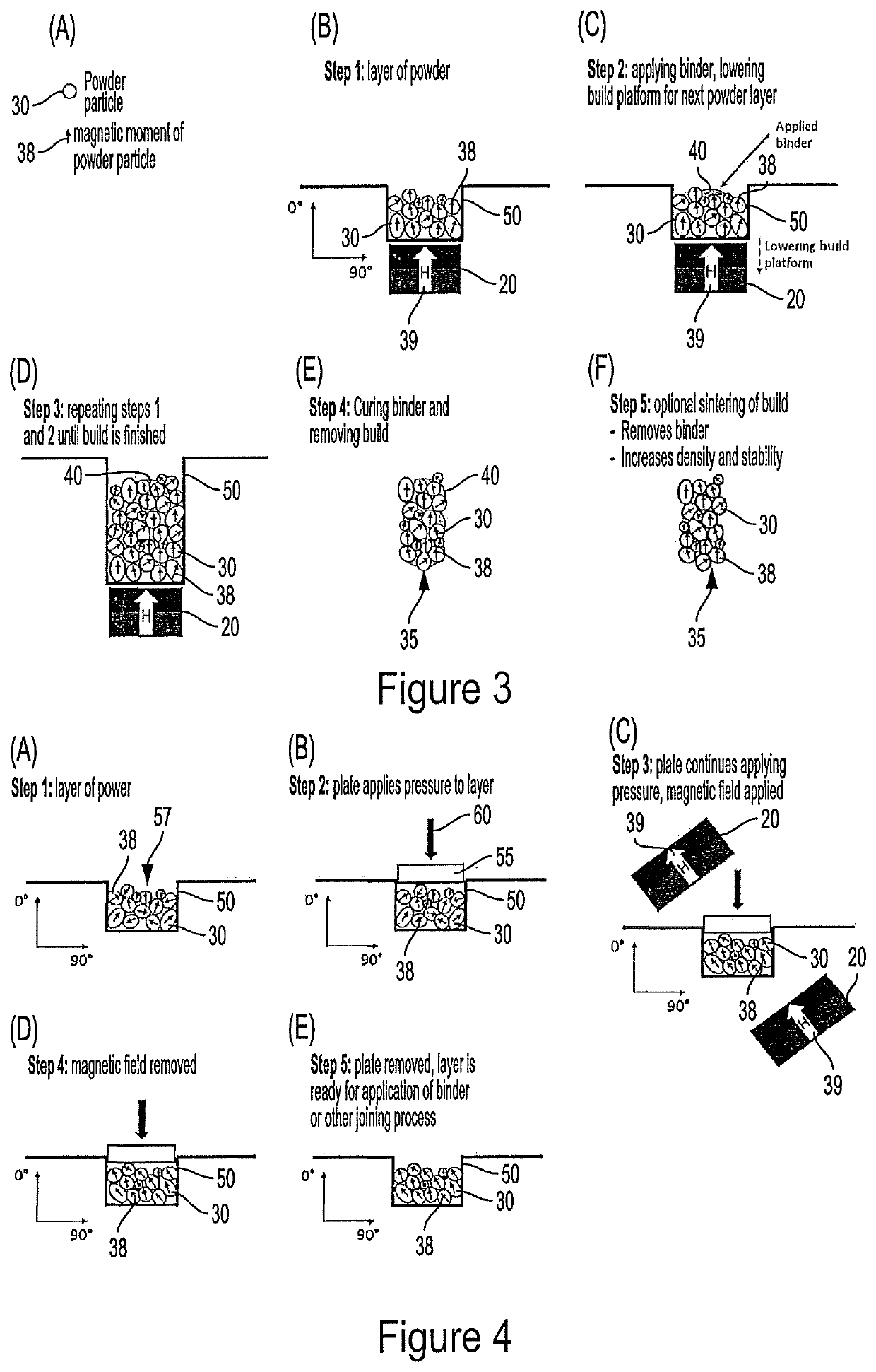
[0076]FIG. 4 demonstrates a preferred method according to the present disclosure for producing a layer 57 with net magnetization in a direction that is not perpendicular to the plane of the layer 57. In step 1 shown in FIG. 4(A), the powder particles 30 have a various magnetic moments 38 and so do not produce a significant net magnetization direction. In step 2 shown in FIG. 4(B), a plate 55 is used to apply compressive pressure 60 to the powder layer 57. In step 3 shown in FIG. 4(C), an external magnetic field 39 produced by magnets 20, previously not present, is applied; simultaneously, the compressive pressure 60 continues to be applied via plate 55 and may be increased...


PUM

PropertyMeasurementUnit
magnetic fieldaaaaaaaaaa
pressureaaaaaaaaaa
magnetic momentsaaaaaaaaaa

Abstract

A method for producing an MSMA, a magnetic material or a magnetic item via additive manufacturing, comprising: (a) providing or forming a layer of magnetic / ferromagnetic particles; (b) applying a magnetic field, having a first three-dimensional (“3D”) magnetic field vector with respect to an origin point of a 3D coordinate system, to the layer of particles or portion thereof, either while pressure is or is not applied to hold the particles in place, to align the magnetic moments of the magnetic particles in the layer or portion thereof during or after the providing or forming of the layer or portion thereof; (c) applying means for binding the layer wherein means for binding may comprise a binder material or complete / partial sintering of the layer; (d) providing or forming a next layer of magnetic / ferromagnetic particulate material on to the previous layer; (e) applying a magnetic field, having a next 3D magnetic field vector with respect to the origin point of the 3D coordinate system, to the next layer of particles or portion thereof, either while pressure is or is not applied to hold the particles in place, to align the magnetic moments of the magnetic particles in the next layer or portion thereof during or after the providing or forming of the next layer or portion thereof; and (f) applying means for binding the next layer wherein means for binding may comprise a binder material or complete / partial sintering of next layer.

Description

CROSS REFERENCE TO RELATED APPLICATIONS[0001]This application claims the benefit of provisional patent application U.S. Ser. No. 62 / 511,164 filed May 25, 2017, which is incorporated by reference herein for all purposes.BACKGROUND OF THE DISCLOSURE[0002]During spreading or deposition of magnetic powder particles during additive manufacturing (AM), powder particles get randomly oriented (see FIG. 1). For certain magnetic materials, a random orientation in bulk parts is not desirable. The magnetic properties of the powder particles might cancel or weaken each other in the bulk part which consists of more than one powder particle and, thus, this weakening or cancellation results in no significant overall magnetic moment of the part built from magnetic particles (see FIG. 1). By orienting or aligning the magnetic powder particles during the build of the part, the magnetic properties of the bulk part will be multiples of the properties of the individual powder particle. This is desirable ...

Claims


Application Information

Patent Timeline
Patent Type & Authority Applications(United States)
IPC IPC(8): H01F41/32H01F10/08H01F1/08H01F1/22H01F41/02
CPCH01F1/22H01F41/32H01F10/08H01F41/0273H01F1/086H01F41/0206B33Y10/00B33Y40/00
Inventor CHMIELUS, MARKUSKRIMER, YUVALMOSTAFAEI, AMIRSTEVENS, ERICATOMAN, JAKUB
Owner UNIVERSITY OF PITTSBURGH
Learn More