Female terminal

a terminal and female technology, applied in the direction of coupling contact members, coupling device connections, electrical devices, etc., can solve the problems of reduced easy failure of terminal connections, and increased wear of plating, so as to ensure the connection reliability of terminals

Active Publication Date: 2020-05-21
AUTONETWORKS TECH LTD +2
View PDF0 Cites 2 Cited by
  • Summary
  • Abstract
  • Description
  • Claims
  • Application Information

AI Technical Summary

Benefits of technology

[0008]The high contact pressure keeps electrical connection at the contact portion between the male terminal and the female terminal when vibration or the like is applied to the fit male terminal and female terminal. If the male terminal is inserted into or withdrawn from the female terminal with such a high contact pressure applied to the male terminal, plating applied to the contact portion between the male terminal and the female terminal is worn. On the other hand, the low contact pressure is lower than the high contact pressure and does not cause the wear of the plating applied to the female terminal at the contact portion between the male terminal and the female terminal even if the male terminal is inserted into or withdrawn from the female terminal.
[0009]The plating applied to the female terminal at the second contact portion is worn where the second contact pressure applying portion applies the high contact pressure to the male terminal. However, this area is affected less by vibration and the like and a connection failure between the male and female terminals is less likely to occur. On the other hand, at the first contact portion where the first contact pressure applying portion for applying the low contact pressure and the male terminal are in contact, the wear of the plating applied to the female terminal can be prevented. Thus, conduction can be ensured while the wear of the plating due to the insertion and withdrawal of the male terminal many times is prevented. Therefore, the connection reliability of the terminals is ensured while the wear of the plating is allowed at the second contact pressure applying portion for applying the high contact pressure, and the wear of the plating is prevented and conduction is ensured even if the male terminal is inserted into and withdrawn from the female terminal many times at the first contact pressure applying portion for applying the low contact pressure.
[0012]However, by applying the high contact pressure not only from the ceiling wall side, but also from the bottom wall side as described above, the male terminal can be inserted into and withdrawn from the female body without the plating of the first contact pressure applying portion being worn even if the male terminal rattles.
[0013]The second contact pressure applying portion may include a second vertical piece vertically extending from the second contact portion toward the bottom wall, and an end surface of the second vertical piece may contact the bottom wall by insertion of the male terminal. With this configuration, the second contact portion of the second contact pressure applying portion in contact with the male terminal is displaced toward the bottom wall when the male terminal is inserted into the female body. Associated with that, the second vertical piece of the second contact pressure applying portion also is displaced toward the bottom wall and the end surface of the second vertical piece comes into contact with the bottom wall. However, the second vertical piece vertically extends from the second contact portion toward the bottom wall and hardly deflects. Thus, if the second vertical piece contacts the bottom wall, the second contact portion is hardly displaced toward the bottom wall. Therefore, the second contact pressure applying portion can apply the high contact pressure to the male terminal.
[0015]According to the female terminal disclosed in this specification, the connection reliability of the terminals can be ensured while anti-vibration measures are taken.

Problems solved by technology

If the male tab terminal needs to be inserted and withdrawn many times, the wear of the plating increases.
However, if the contact pressure of the leaf spring of the female terminal is lowered, the connection reliability of the terminals is reduced and a connection failure of the terminals easily occurs due to vibration or the like.

Method used


Image

  • Female terminal
  • Female terminal
  • Female terminal

Examples


Embodiment Construction

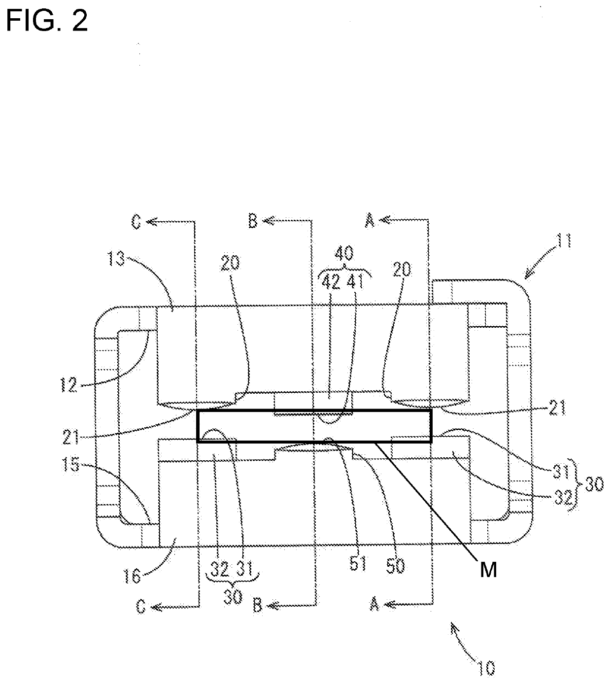
[0025]An embodiment is described with reference to FIGS. 1 to 9.

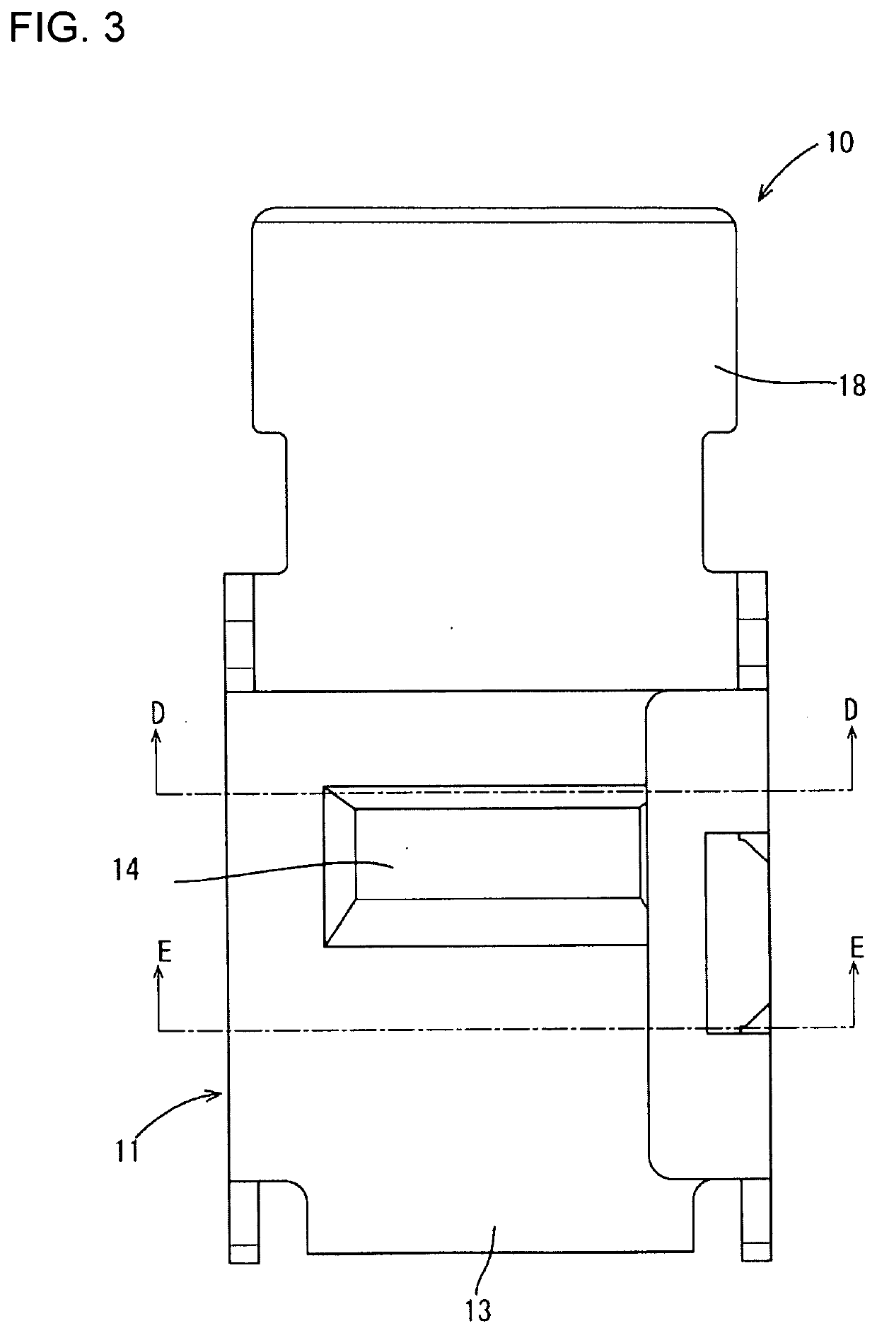
[0026]A female terminal 10 of this embodiment is formed by stamping and bending a copper plate. Further, plating of silver or the like is applied to the processed female terminal 10. As shown in FIG. 1, the female terminal 10 includes a female body 11 and a wire connecting portion 18 provided behind the female body 11. The female terminal 10 is fit to a male terminal M.

[0027]The male terminal M is plate-like and formed such as by stamping a plate. Further, plating of silver or the like is applied to the processed male terminal M.

[0028]As shown in FIG. 5, the female body 11 is box-shaped and open in a front-rear direction. A ceiling wall 12 and a bottom wall 15 facing each other in a vertical direction are provided inside the female body 11. In the following description, a fitting direction of the female terminal 10 to the male terminal M is referred to as a forward direction, and a direction from the bottom wall 15 towa...


PUM


Abstract

A female terminal (10) includes a female body (11) having a ceiling wall (12) and a bottom wall (15) facing each other. First contact pressure applying portions (20) apply a contact pressure by contacting a male terminal from the side of the ceiling wall (12), and second contact pressure applying portions (30) apply a contact pressure by contacting the male terminal from the side of the bottom wall (15). First contact portions (21) of the first contact pressure applying portions (20) and second contact portions of the second contact pressure applying portions (30) are shifted from each other in the front-rear direction. The contact pressure applied by the first contact pressure applying portions (20) is lower than the contact pressure applied by the second contact pressure applying portions (30).

Description

BACKGROUNDField of the Invention[0001]This specification relates to a female terminal.Related Art[0002]Japanese Unexamined Patent Publication No. 2014-53205 discloses a female terminal formed by press-working and bending a plate. Further, plating is applied to the processed female terminal. The female terminal includes a rectangular tubular box into which a male tab terminal is inserted. A conductor crimping portion is provided behind the box and is to be crimped to a conductor of a wire. A leaf spring is provided on an upper wall inside the box and resiliently contacts the male tab terminal. A tab receiving portion is provided on a lower wall inside the box and contacts the male tab terminal.[0003]The male tab terminal is formed by press-working and bending a plate. Further, plating is applied to the processed male tab terminal. The male tab terminal includes a bar-shaped male body.[0004]The male body that is inserted into the box of the female terminal is sandwiched between the le...

Claims


Application Information

Patent Timeline
Patent Type & Authority Applications(United States)
IPC IPC(8): H01R13/115H01R13/11
CPCH01R13/113H01R13/115
Inventor KITAOKA, KENICHI
Owner AUTONETWORKS TECH LTD
Why Eureka
Try Eureka