Column and beam connection structure and method

a technology of beam connection and beam, which is applied in the direction of construction, building construction, etc., can solve the disadvantages of material cost and filler, and achieve the effects of reducing labor costs, shortening manufacturing period, and reducing labor costs

Inactive Publication Date: 2018-08-09
NIPPON STEEL & SUMIKIN METAL PROD CO LTD
View PDF1 Cites 24 Cited by
  • Summary
  • Abstract
  • Description
  • Claims
  • Application Information

AI Technical Summary

Benefits of technology

[0027]According to the present invention described above, the external diaphragm can be installed in the steel pipe column in a stable state using a mechanical installation means without welding, so that it is possible to prevent the external diaphragm from falling down due to gravity by virtue of a frictional force exerted between the steel pipe column and the external diaphragm. In addition, in the event of an earthquake, a vertical acting force makes it possible to prevent the external diaphragm from moving in a vertical direction as significantly as a problem occurs in force transfer. In particular, since the external diaphragm can be fixed to the steel pipe column without welding, it is possible to reduce a work labor in the manufacturing. Furthermore, it is possible to reduce cost of the labor necessary for maintaining the quality of the welded portion and cost of various devices such as an inspection device and shorten manufacturing period. For this reason, it is possible to perform construction with reduced energy consumption and employ an environmentally friendly connection method. Moreover, since a process of filling a filler such as mortar resin can be eliminated, it is possible to further reduc

Problems solved by technology

In addition, the material cost for the fi

Method used


Image

  • Column and beam connection structure and method
  • Column and beam connection structure and method
  • Column and beam connection structure and method

Examples


Embodiment Construction

[0047]A connection structure between a steel pipe column and a beam according to the present invention will now be described in details with reference to the accompanying drawings.

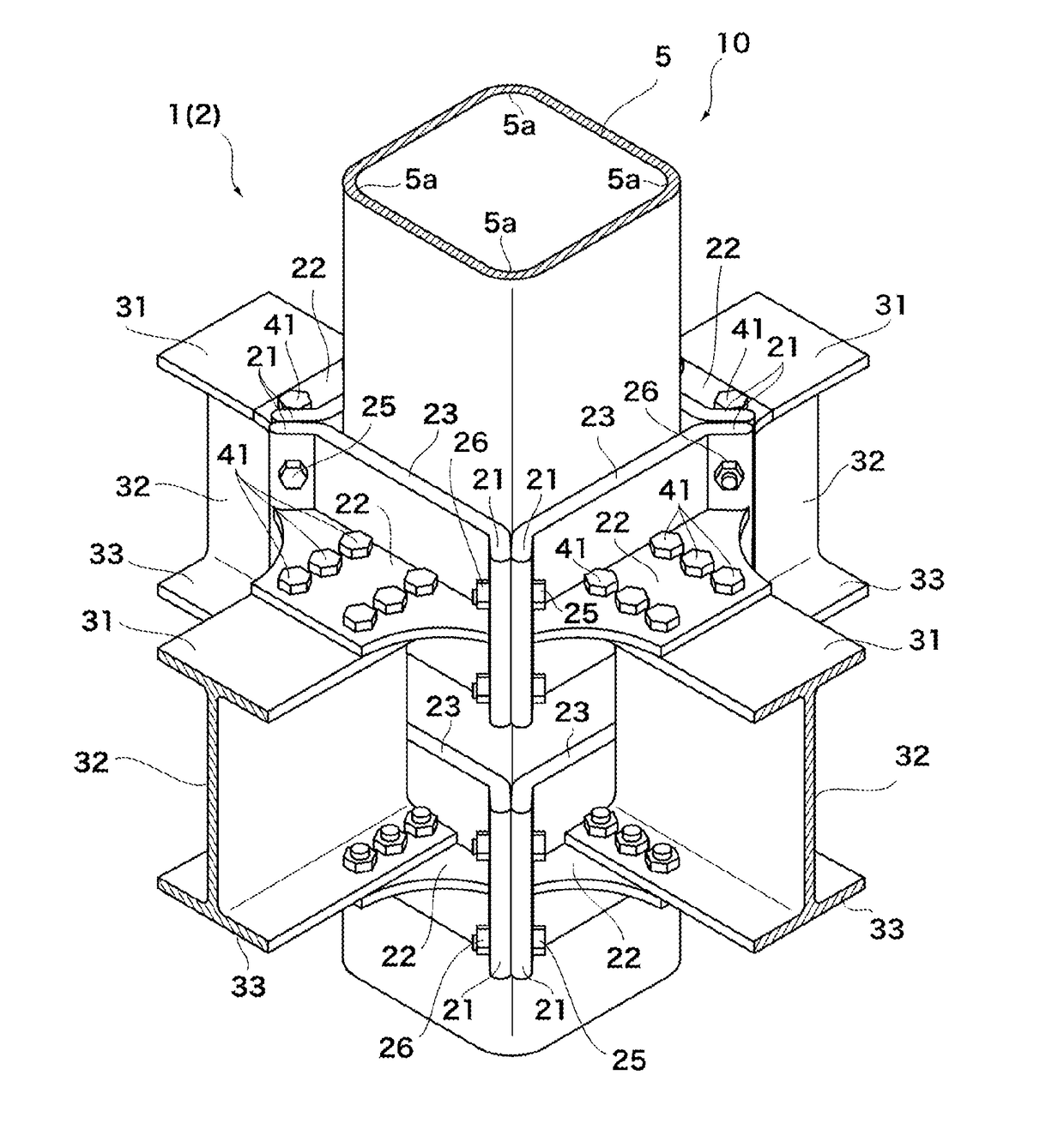
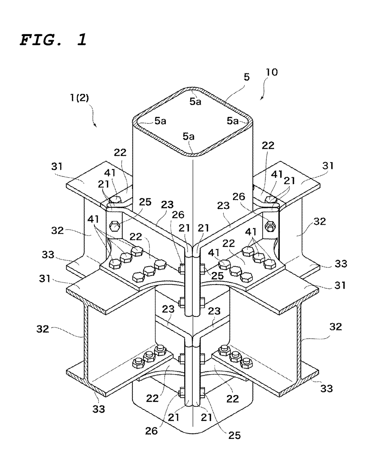
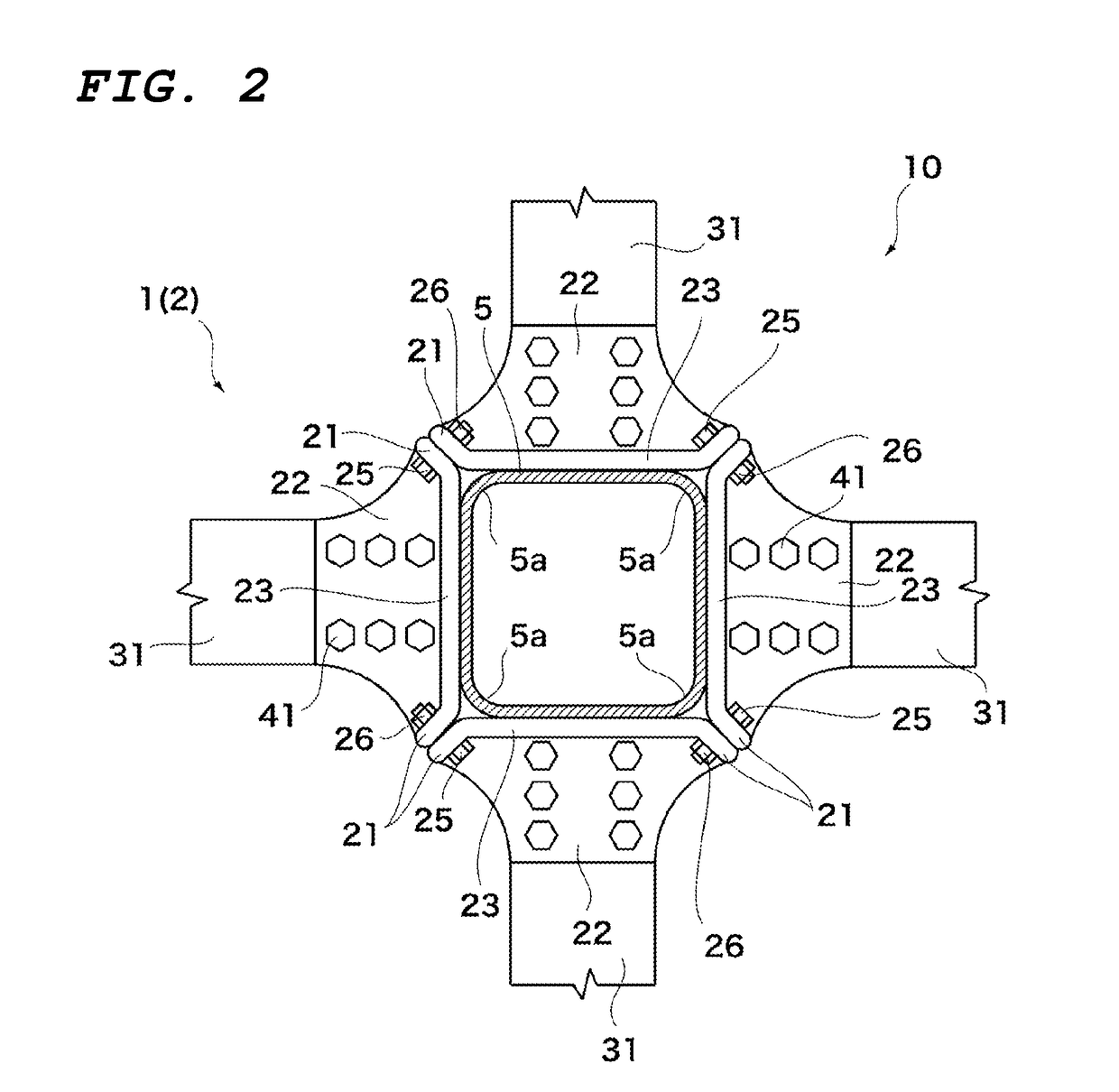
[0048]FIG. 1 is a perspective view illustrating the connection structure 10 between the steel pipe column and the beam according to the present invention, FIG. 2 is a cross-sectional plan view of FIG. 1, and FIG. 3 is a side view of FIG. 1.

[0049]In the connection structure 10 between the steel pipe column and the beam according to the present invention, a steel H-beam 3 is arranged perpendicularly to a column surface of the steel pipe column 5 using an external diaphragm 1. Alternatively, without limiting thereto, the steel H-beam 3 may be arranged obliquely to the column surface of the steel pipe column 5 in a vertical direction or a left-right direction.

[0050]The steel pipe column 5 is a steel pipe having a rectangular cross-sectional shape with a predetermined plate thickness as a columnar structure for...


PUM


Abstract

A column and beam connection structure for connecting a steel H-beam to a column uses an external diaphragm. The external diaphragm includes a plurality of divided diaphragm segments such that each diaphragm segment has a column plate abutting on the column. A diaphragm segment which is arranged along the steel H-beam among the plurality of divided diaphragm segments has a beam plate installed in a flange of the steel H-beam. The beam plate has an end portion in which the column plate is provided. A joining surface between the diaphragm segments is placed in a vicinity of a corner portion of the column so that only the column plate of one of the diaphragm segments abuts on each column surface of the column. A joining member fastens to fix between the diaphragm segments such that contact pressure is applied from the column plates to the surface of the column.

Description

FIELD OF THE INVENTION[0001]The present invention relates to a column and beam connection structure and method for connecting a column to a steel H-beam using an external diaphragm.BACKGROUND OF THE INVENTION[0002]In the prior art, a diaphragm construction method is applied to steel pipe columns here and there of a building structure for reinforcement and deformation prevention purposes, in many cases. In a through diaphragm construction method as one of such diaphragm construction methods, the steel pipe column is cut to match upper and lower +s of the steel H-beam, and a diaphragm is inserted and welded to the steel pipe column, so that they are assembled. The steel H-beam is installed by cutting out a portion for connecting to the steel pipe column as a beam bracket in advance, welding the upper and lower flanges to the through diaphragm, and welding its web to a skin plate of the steel pipe column. The beam bracket installed in the diaphragm and the steel H-beam are joined to ea...

Claims


Application Information

Patent Timeline
IPC IPC(8): E04B1/24E04B1/58E04B1/21
CPCE04B1/24E04B1/5812E04B1/215E04B2001/2415E04B2001/2418E04B1/2403E04B2001/2406E04B2001/2448E04B2001/2454E04B2001/2478
Inventor UNO, NOBUYOSHIINOUE, KAZUOSHINMURA, HIROYUKISATO, YUGOOKADA, TADAYOSHI
Owner NIPPON STEEL & SUMIKIN METAL PROD CO LTD
Why Eureka
Try Eureka