Omni-directional wheels and methods and vehicles employing same

Inactive Publication Date: 2008-04-17
AIRTRAX
View PDF33 Cites 28 Cited by
  • Summary
  • Abstract
  • Description
  • Claims
  • Application Information

AI Technical Summary

Benefits of technology

[0112] In one or more preferred embodiments of the invention, it is an object to equip vehicles, such as described herein, with omni-directional wheels that exhibit constant vehicle ride height, low wheel vibration, and high load capacity. In other embodiments it is an object to provide a design for rollers for omni-directional wheels that produces little or no wheel rotation-induced ride height fluctuation for an expected range of loading. In certain preferred embodiments, it is an object to provide low-vibration omni-directional wheels on forklift, scissor-lift and wheelchair vehicles. In still additional embodiments, it is an object to provide a method for designing omni-directional wheel rollers to provide low vibration performance when used on an omni-directional vehicle.
[0113] In some preferred embodiments, this invention improves the ride performance of omni-directional vehicles, reducing vibration and r

Problems solved by technology

Despite the known commercial need for omni-directional vehicles, initial omni-directional technologies did not achieve widespread commercial success due in part to the vibration and uneven ride produced by early omni-directional wheel designs.
Although, as aforesaid, the commercial viability of omni-directional wheels has been improved dramatically by various relatively recent Airtrax, Inc. innovations, the actual implementation of omni-directional wheels, much like the implementation of any major structural improvement in a given technology, can require substantial time and effort.
Such changes require considerable mechanical and/or engineering skill as well as significant labor times and/or costs.
Although, over the years, prior art munitions handling equipment has been used with varying degrees of success for transporting, loading, and unloading munitions cargo, there are various unresolved drawbacks in the art related to the maneuverability of conventional munitions handling vehicles as well as their mechan

Method used


Image

  • Omni-directional wheels and methods and vehicles employing same
  • Omni-directional wheels and methods and vehicles employing same
  • Omni-directional wheels and methods and vehicles employing same

Examples


Embodiment Construction

[0158] For a more complete understanding of the present invention and advantages thereof, reference is now made to the following description of various illustrative and non-limiting embodiments thereof, taken in conjunction with the accompanying drawings in which like reference numbers indicate like features.

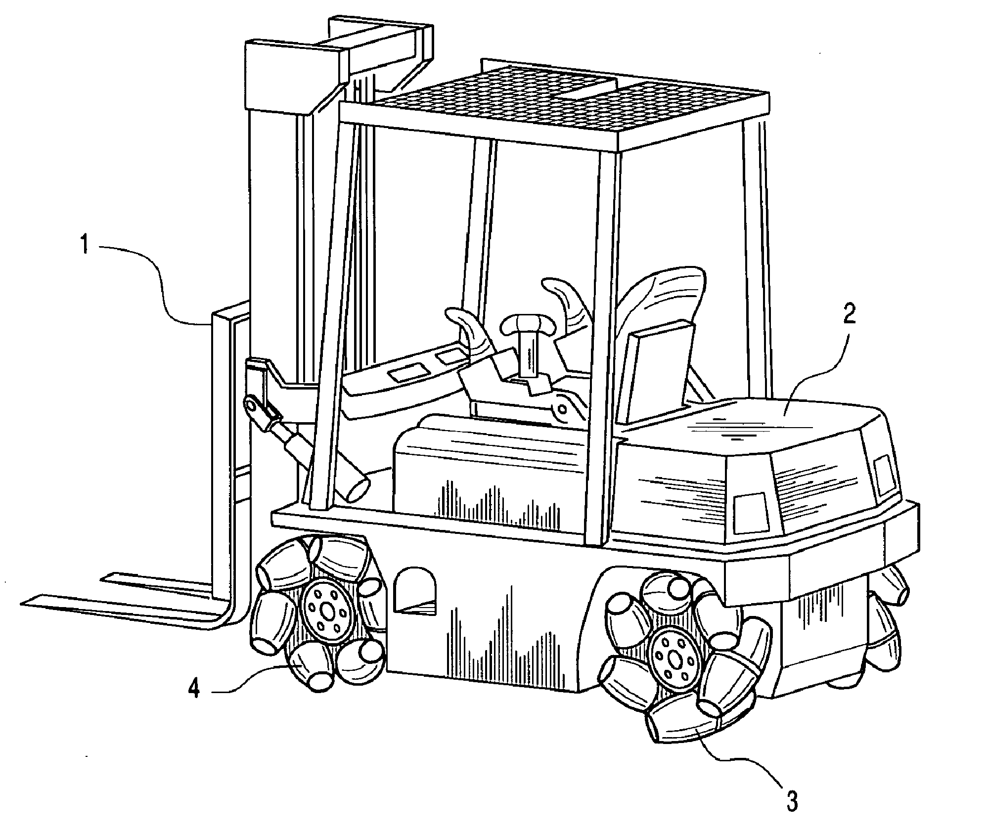
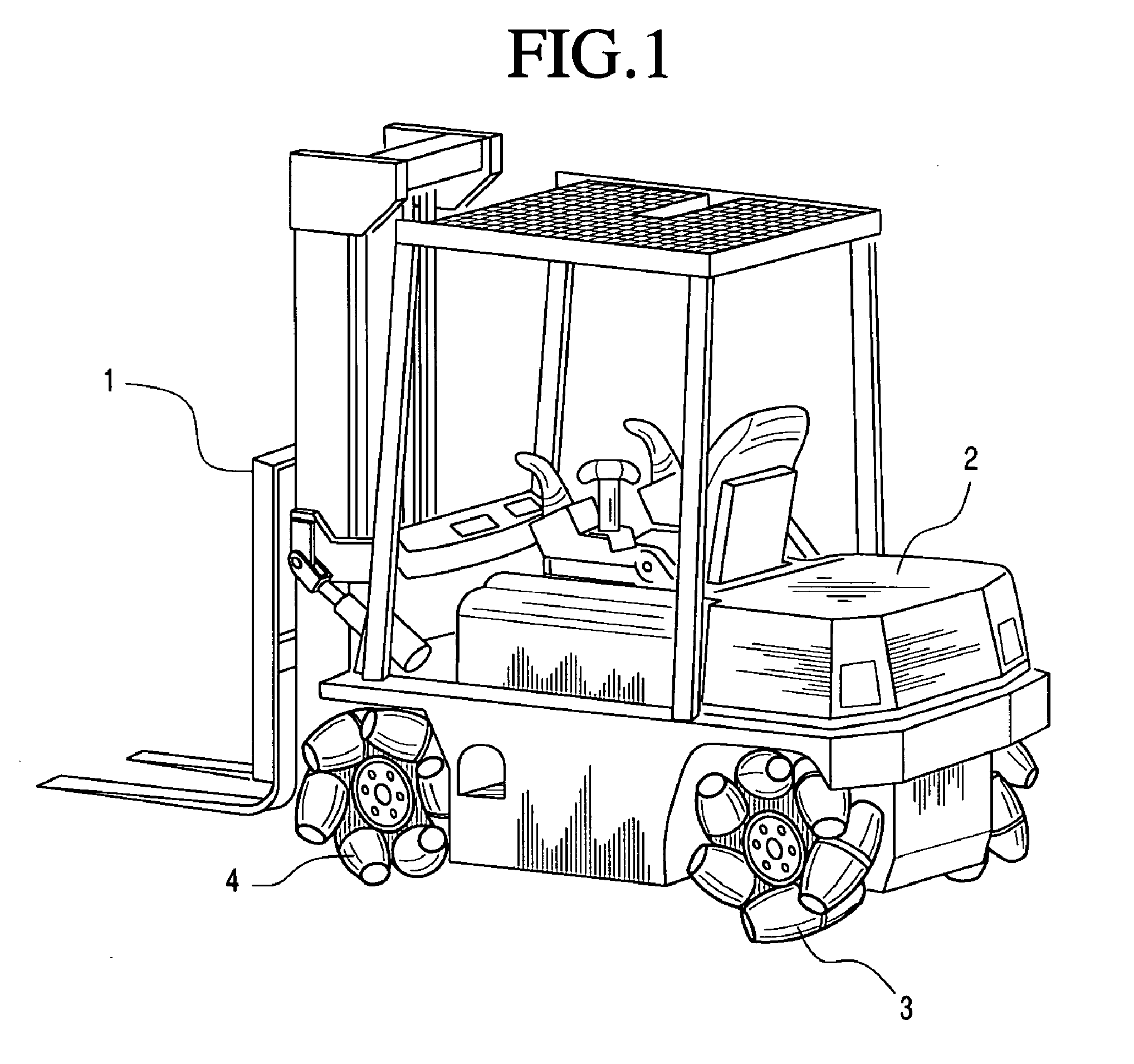
[0159] Referring initially to FIG. 1, a forklift-type vehicle employing a plurality of omni-directional wheels according to one embodiment of the subject invention is illustrated therein. As such, the depiction of such a forklift is primarily intended to illustrate one environment in which one or more embodiments of the invention find utility. In this regard, FIG. 1 is not intended to be limiting as many other vehicle types (or no vehicle at all) can be combined with the instant invention(s).

[0160] As illustrated in FIG. 1, forklift 1 is generally comprised of a vehicle chassis 2, three or more omni-directional wheels 3, wheel axles 4 which connect wheels 3 to chassis 2, and d...


PUM

PropertyMeasurementUnit
Lengthaaaaaaaaaa
Lengthaaaaaaaaaa
Poweraaaaaaaaaa

Abstract

Omni-directional vehicles and wheels therefore including methods of constructing same. In alternative embodiments, omni-direction wheel modules for imparting omni-directional locomotional capabilities to vehicles and objects. In further alternative embodiments, apparatus and methods for transporting and loading and off-loading munitions utilizing specialized, omni-directional capable vehicles for improved efficiency and/or safety.

Description

RELATED APPLICATION DATA [0001] This application is a continuation of and claims the benefit of priority of copending U.S. patent application Ser. No. 11 / 025,838, filed on Dec. 30, 2004, entitled OMNI-DIRECTIONAL WHEELS AND METHODS AND VEHICLES EMPLOYING SAME, which is a continuation-in-part and claims the benefit of priority of U.S. patent application Ser. No. 09 / 827,173, filed Apr. 6, 2001, entitled HYBRID POWER SUPPLY MODULE, which claims the benefit of priority of U.S. patent application Ser. No. 60 / 197,391, filed Apr. 14, 2000, similarly titled; and is a continuation-in-part of U.S. patent application Ser. No. 10 / 953,072, filed Sep. 30, 2004, entitled VEHICLES AND CONTROL SYSTEMS THEREOF WITH ADJUSTABLE STEERING AXES, which claims the benefit of priority of U.S. patent application Ser. No. 60 / 506,723, filed Sep. 30, 2003, entitled VEHICLE WITH ADJUSTABLE STEERING AXIS; and is a continuation-in-part of U.S. patent application Ser. No. 10 / 647,122, filed Aug. 25, 2003, entitled RE...

Claims


Application Information

Patent Timeline
IPC IPC(8): B65G65/00B65G67/00B60B19/00B66F9/075B62D7/00
CPCB60B19/003B66F9/06B60B2310/202B60B2310/212B60B2310/302B60B2360/10B60B2360/32B60B2360/324B60B2360/3412B60B2360/36B60B2360/50B60B2360/70B60B2380/12B60B2380/14B60Y2200/15B60B19/125
Inventor FENELLI, NICHOLASMULLOWNEY, ROBERT
Owner AIRTRAX
Why Eureka
Try Eureka