
Friction ring element, friction ring set for arranging on the wheel web of a track wheel, and track wheel brake

a technology of friction rings and friction rings, which is applied in the direction of braking discs, mechanical equipment, transportation and packaging, etc., can solve the problems of complex casting moulds and production of friction rings, and achieve the effect of high connection force, quick and safe inspection

Inactive Publication Date: 2020-05-28
FAIVELEY TRANSPORT WITTEN GMBH
View PDF0 Cites 0 Cited by
  • Summary
  • Abstract
  • Description
  • Claims
  • Application Information

AI Technical Summary

Benefits of technology

The invention is about creating friction ring elements for a track wheel brake system. The goal is to create a simple and cost-effective way to produce these elements. The friction rings should be easily equipped with linking elements that can cool and connect the rings to the wheel web. The linking elements should be simple bolts that can be produced using a machining process. Connecting elements can also be used to interlock two friction rings at a wheel web. These elements are designed to withstand high loads and can be easily inspected during maintenance. The technical effects are an improved track wheel brake system that is cost-effective to manufacture and safe to use.

Problems solved by technology

The casting production of such friction ring elements requires technically complex casting moulds, in particular, if the friction ring elements have mouldings with which they abut on the wheel web of the track wheel, and if the friction ring elements, for example, must have cooling fins to cool the friction rings.
A disadvantage of this embodiment is that the materials for the friction ring and the linking elements must be matched to one another in such a way that a (cost-effective) welding process is applicable.

Method used


Image

  • Friction ring element, friction ring set for arranging on the wheel web of a track wheel, and track wheel brake
  • Friction ring element, friction ring set for arranging on the wheel web of a track wheel, and track wheel brake
  • Friction ring element, friction ring set for arranging on the wheel web of a track wheel, and track wheel brake

Examples


Embodiment Construction

[0020]Further measures improving the invention are shown in more detail below together with the description of preferred embodiments of the invention with reference to the figures.

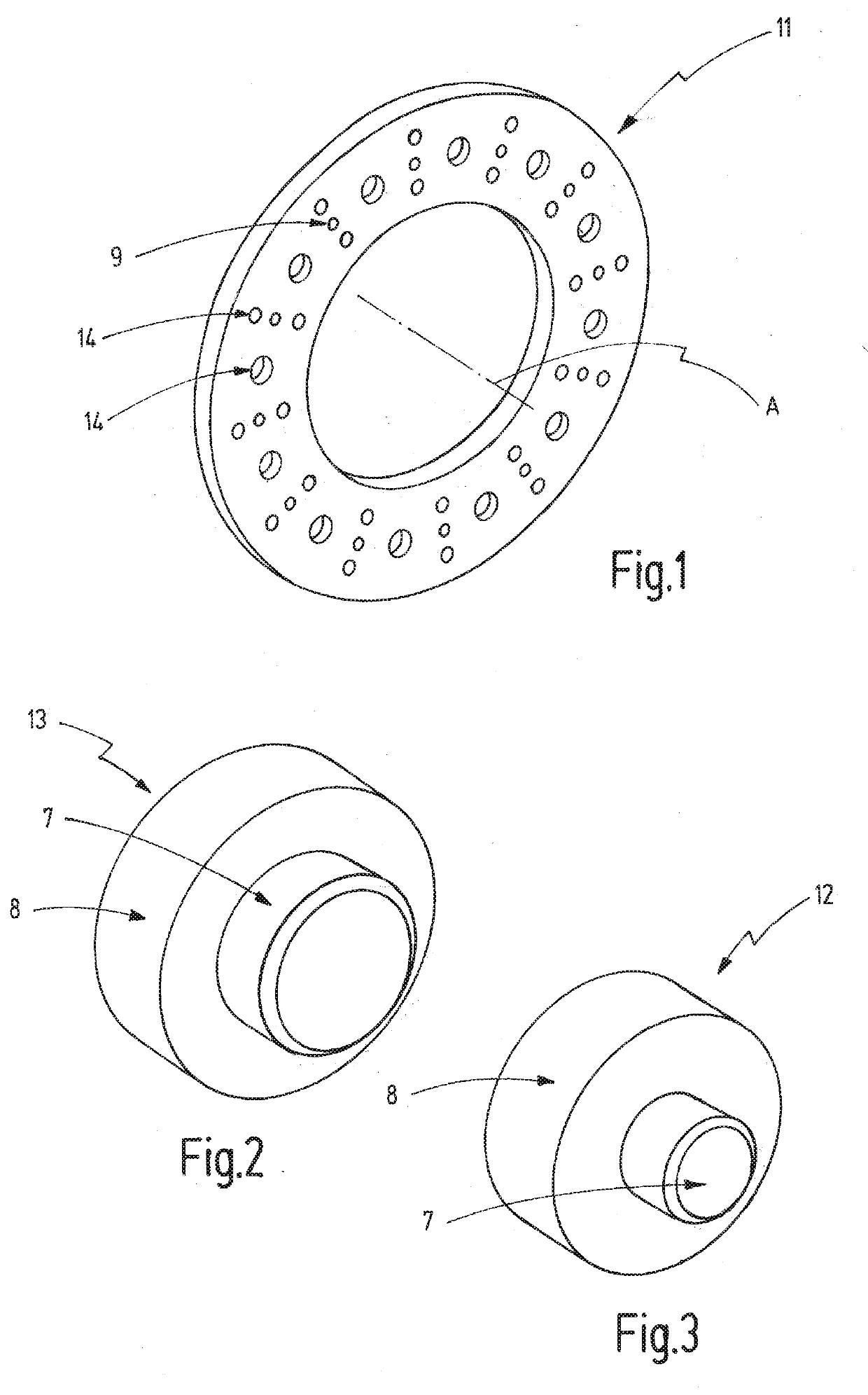
[0021]FIG. 1 shows a perspective view of a friction ring,

[0022]FIG. 2 shows a perspective view of a connecting element,

[0023]FIG. 3 shows a perspective view of a cooling element,

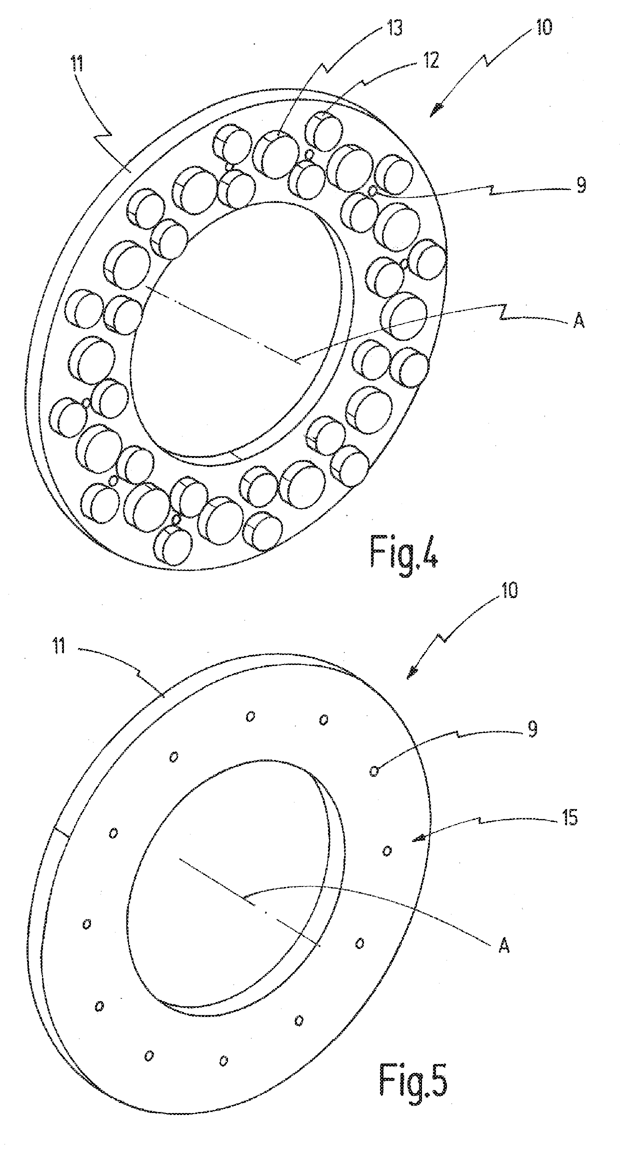
[0024]FIG. 4 is a perspective view of a friction ring element as a raw component on the connection element side,

[0025]FIG. 5 shows a perspective view of a friction ring element as a raw part on the frictional surface side,

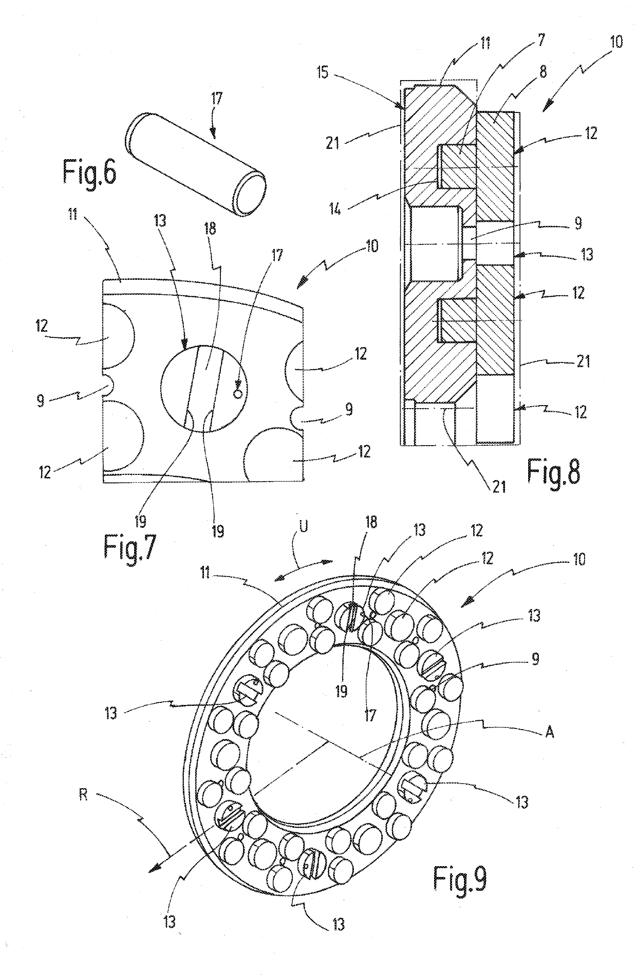
[0026]FIG. 6 shows a pin for a positive rotation lock of a connecting element,

[0027]FIG. 7 shows a plan view of a detailed section of a connecting element which is pinned, arranged on a friction ring,

[0028]FIG. 8 shows a sectional view of a machine finished friction ring element,

[0029]FIG. 9 shows a perspective view a finished friction ring element of the connection element side,

[0030]FIG. 10 shows a perspective v...


PUM


Abstract

In order to provide a development of friction ring elements for a friction ring set for arranging on the wheel web of a track wheel in order to form a track wheel brake, wherein the friction ring elements can be simply and cost-effectively produced and can be easily fitted with linking elements, a friction ring element (10) is proposed for a friction ring set (200) for arranging on the wheel web (2) of a track wheel (1) for a railway vehicle in order to form a track wheel brake (100), wherein the friction ring element (10) has a friction ring (11) and multiple linking elements (12, 13) designed as separate components and arranged on the friction ring (11), and wherein at least some of the linking elements (12, 13) are force-lockingly connected to the friction ring (11).

Description

[0001]The present invention relates to a friction ring element for a friction ring set and to such a friction ring set for arranging on the wheel web of a track wheel for a rail vehicle in order to form a track wheel brake and also relates to such a track brake.PRIOR ART[0002]EP 1 460 283 A1 shows, for example, a friction ring element arranged on the wheel web of a track wheel for a rail vehicle in order to form a track wheel brake. The friction ring elements are made of cast steel and have mouldings that form cooling fins and with which the friction ring elements abut on the surface of the wheel web. The mouldings also serve to accommodate through-bolts in order to screw the friction ring elements against each other by passing the through bolts through holes in the wheel web. The shown geometry of the friction ring elements can be technically reasonably produced only with a relatively expensive original mould procedure.[0003]Further friction ring elements for arranging on the wheel...

Claims


Application Information

Patent Timeline
IPC IPC(8): F16D65/12B61H5/00B60B17/00
CPCF16D65/124B60B17/00B61H5/00F16D2065/1392F16D2065/1384F16D2200/003F16D2200/0021F16D2250/00F16D65/128F16D2065/1328F16D2065/136F16D65/12
Inventor IMHOF, PHILIPPMEHLAN, ANDREASSTROETMANN, ANDREAS
Owner FAIVELEY TRANSPORT WITTEN GMBH
Learn More