Lever-fitting type connector

a connector and lever-type technology, applied in the direction of coupling device connection, coupling/disconnecting parts, electrical apparatus, etc., can solve the problems of difficult to bend the stopper piece at the time of releasing the lock, and the failure to include a lock mechanism for holding the connector, etc., to achieve the effect of improving the operability of the release unit and facilitating the pressing of the lock release uni

Inactive Publication Date: 2008-11-11
YAZAKI CORP +1
View PDF9 Cites 8 Cited by
  • Summary
  • Abstract
  • Description
  • Claims
  • Application Information

AI Technical Summary

Benefits of technology

[0005]It is, therefore, an object of the present invention to provide a lever-fitting type connector that can ensure high connecting force for connecting two connector housings to each other and good lock releasing operability.
[0019]With the above configuration, since the release-operation concave portion that enables operating the lock releasing unit is formed in the waterproof cover, it is possible to easily press the lock releasing unit of the anti-rotation lock by inserting a finger into this release-operation concave portion and to improve release operability.

Problems solved by technology

Although the above-state conventional connector is configured to stop rotation of the cam bolt at a position at which the paired connectors are fitted into each other, it fails to include a lock mechanism for holding fitting of these connectors.
However, if force is applied to a grip of the cam bolt, considerably strong force is applied to the insertion hole of the cam bolt.
If a stopper piece to be stopped at the cam bolt, for example, is provided as the lock mechanism at connector side and this stopper is made stronger, it is difficult to bend the stopper piece at the time of releasing the lock.
As a result, lock releasing operability may possibly be deteriorated.
If such a stopper piece is employed as the lock mechanism, it is difficult to simultaneously satisfy improvement in locking force and reduction in lock releasing force.

Method used


Image

  • Lever-fitting type connector
  • Lever-fitting type connector
  • Lever-fitting type connector

Examples


Embodiment Construction

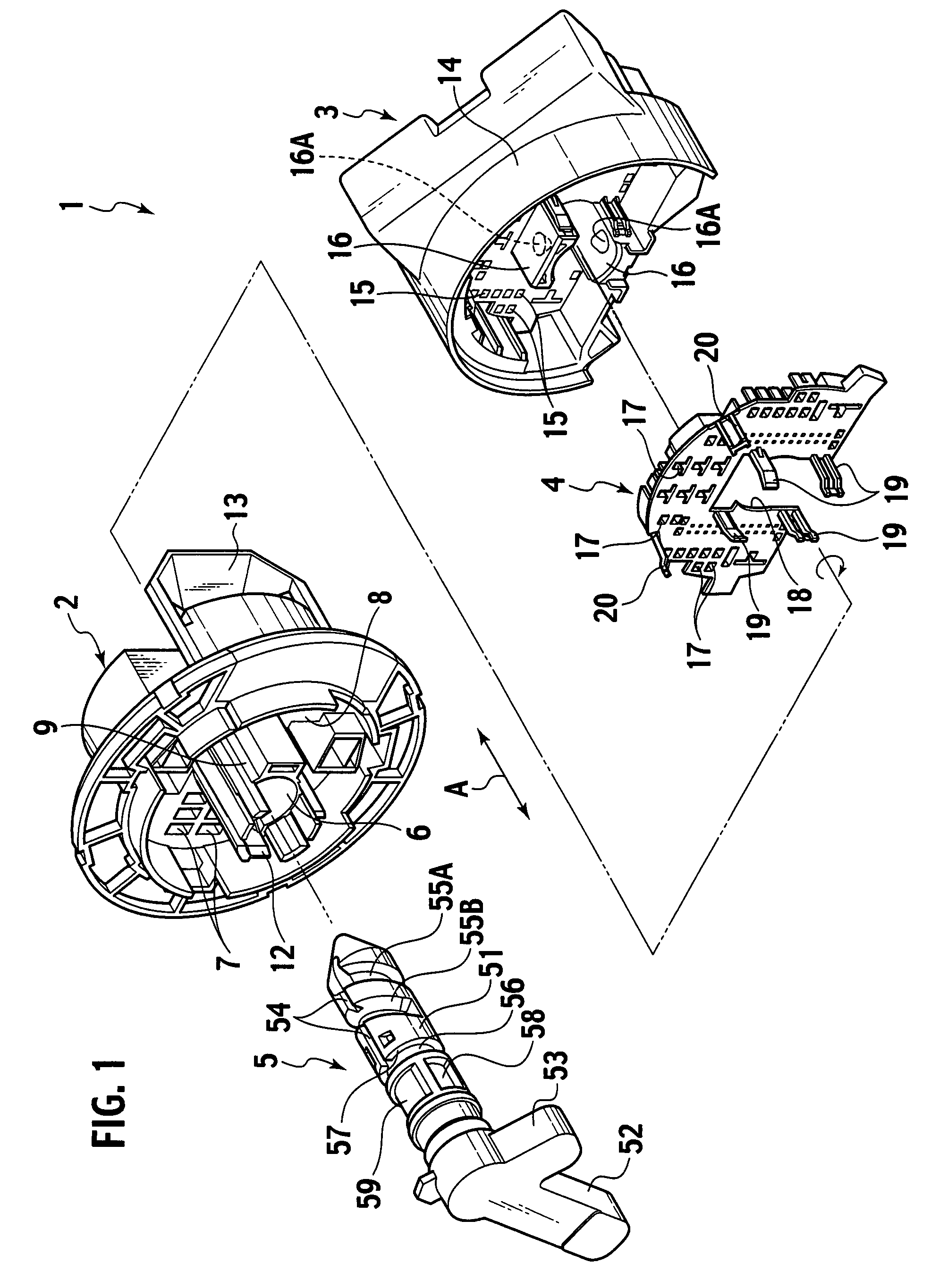
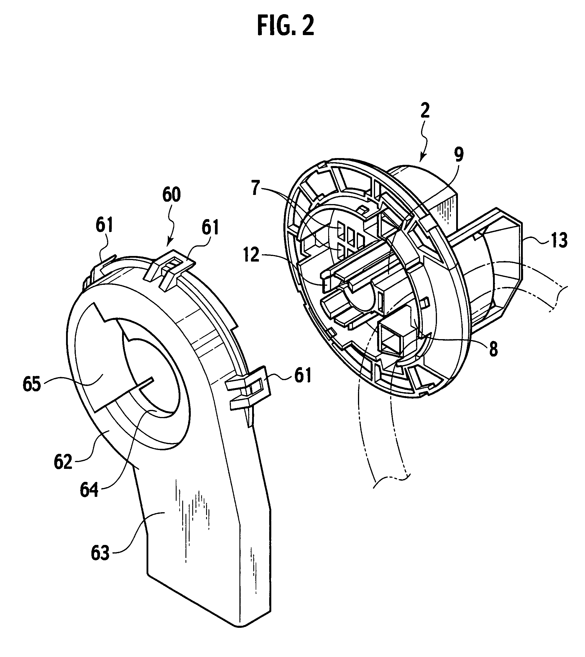
[0033]A lever-fitting type connector according to an embodiment of the present invention is explained below in detail.

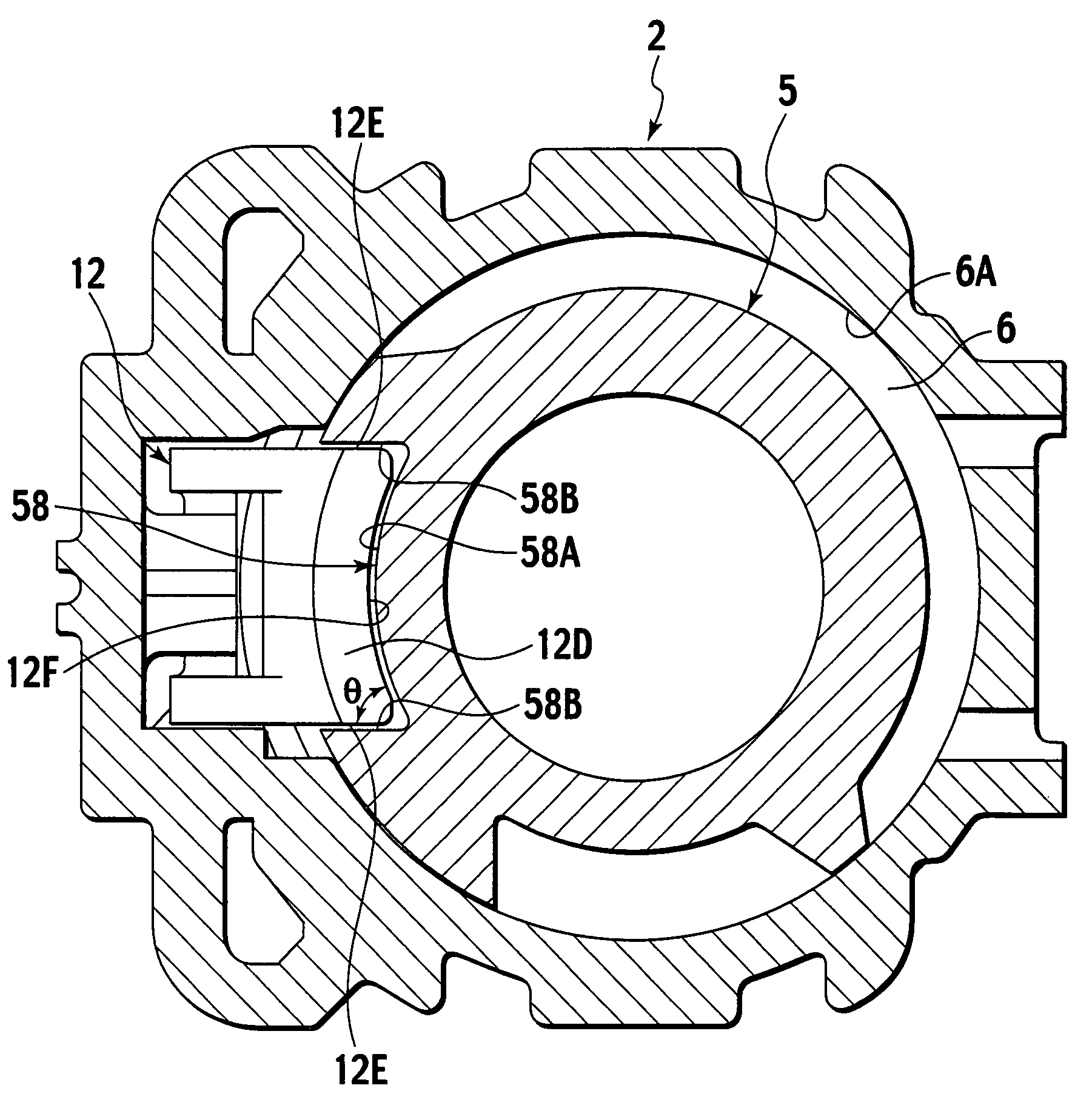
[0034]The outline of the lever-fitting type connector according to the embodiment of the present invention is as follows. A lever having a rod-like part rotatably inserted into and held by a female housing that serves as a first connector housing is rotated, whereby a male housing serving as a second connector housing is drawn and the both connector housings are fitted into each other. An insertion hole for inserting the lever is provided in the female housing. On an inner wall of this insertion hole, an anti-rotation lock that prevents rotation of the lever when the female and male connector housings are fully engaged (connected) is provided. Further, a rotation-locking concave portion that serves as an abutted member is formed on a circumferential surface of the lever to correspond to this anti-rotation lock.

[0035]On the inner wall of this insertion hole, not only ...


PUM


Abstract

A lever-fit connector, wherein a rotation prevention lock (12) preventing a lever (5) from being rotated when male and female connector housing are fitted (joined) to each other is installed in the inner wall (6A) of a lever insert hole (6) in a female housing (2). A rotation lock recessed part (58) in which the rotation lock part (12D) of the rotation prevention lock (12) is engageably stored is formed in the peripheral surface of the lever (5). The angle of the rotation lock part (12D) is set so that the rotation lock part (12D) is drawn to the lever (5) side in excessive rotation by bringing the rotation lock part (12D) into contact with the side wall surface (58B) of the rotation lock recessed part (58).

Description

TECHNICAL FIELD[0001]The present invention relates to a lever-fitting type connector capable of fitting or disconnecting a female connector and a male connector into or from each other by a lever rotating operation.BACKGROUND ART[0002]There is conventionally known a connector having a fitting-operation cam bolt (lever) for fitting a female connector into a male connector by rotating the cam bolt (Japanese Utility Model Examined Publication No. H07-41103). This connector is configured so that cam-bolt insertion holes are formed in the both connectors and a protrusion to be accommodated in a screw groove formed on a circumferential surface of the cam bolt is provided in the insertion hole of one of the connectors. The connector is moved toward the other connector by rotating the cam bolt, thereby fitting the paired connectors into each other.DISCLOSURE OF THE INVENTION[0003]Although the above-state conventional connector is configured to stop rotation of the cam bolt at a position at ...

Claims


Application Information

Patent Timeline
Patent Type & Authority Patents(United States)
IPC IPC(8): H01R13/62
CPCH01R13/621H01R13/631H01R13/639H01R13/62938H01R13/6295H01R13/62955
Inventor IKEYA, KENICHITAKAHASHI, TSUNEYUKIYONEDA, TAKAHIROSAWADA, RYOSASAKI, YASUHIROYOSHIMURA, KENITO, NOZOMITANAKA, SHIGERU
Owner YAZAKI CORP
Why Eureka
Try Eureka