Connecting device for wound protection dressing, and wound protection dressing

Inactive Publication Date: 2020-06-11
WAN MIANSHUI
View PDF0 Cites 11 Cited by
  • Summary
  • Abstract
  • Description
  • Claims
  • Application Information

AI Technical Summary

Benefits of technology

[0033]Advantageous Effects: The invention connects the first pipe joint and the second pipe joint by connecting the ball head and the ball shell, and connects the first through hole and the second through hole, thereby providing a method for avoiding pressing of the skin and

Problems solved by technology

The butt joint ball head and the ball shell adopt a double-layer ball body, the strength is higher,

Method used


Image

  • Connecting device for wound protection dressing, and wound protection dressing
  • Connecting device for wound protection dressing, and wound protection dressing
  • Connecting device for wound protection dressing, and wound protection dressing

Examples


Example

First Embodiment

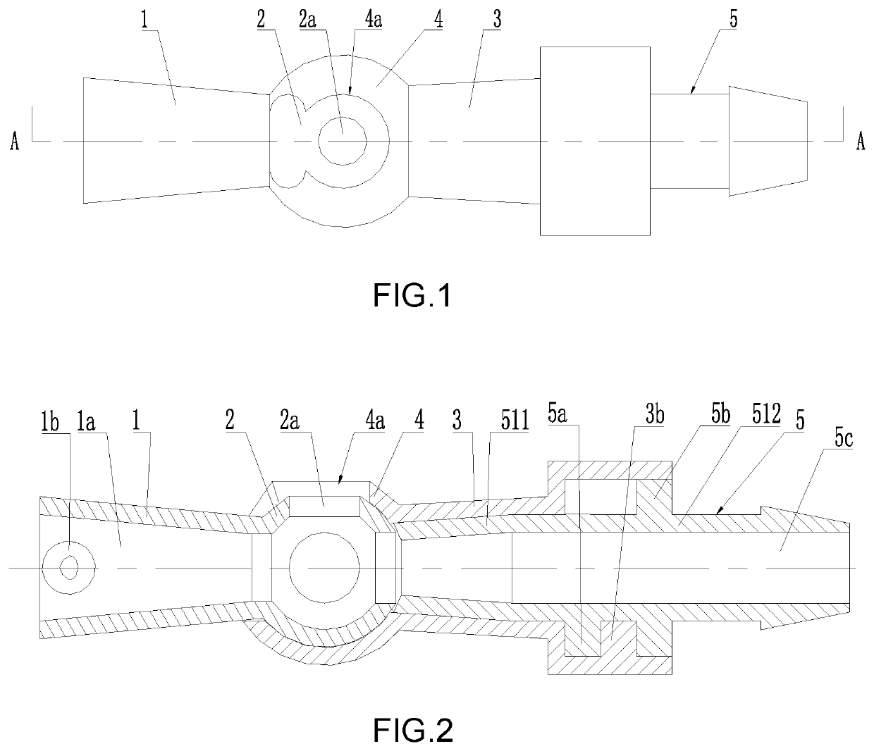
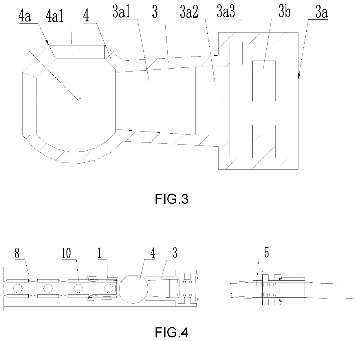
[0050]As shown in FIG. 1, as shown in FIG. 2 and FIG. 3, the embodiment of the invention provides a connecting device for a wound dressing, a first tube joint 1 and a second tube joint 3, a first through hole 1a penetrating through the two ends of the first tube joint 1 is formed in the first tube joint 1, a second through hole 3a penetrating through the two ends of the second tube joint 3 is also formed in the second tube joint 3, a hollow ball head 2 is integrally formed at one end of the first tube joint 1, and an inner cavity of the ball head 2 is communicated with the first through hole 1a of the first tube joint 1. In the embodiment, the first tube joint 1 and the ball head 2 are integrally formed by medical silica gel or medical rubber. At least one through hole 2a is formed in the ball head 2, the number and the position of the through hole 2a are not limited, and a person skilled in the art can ensure that the first through hole 1a and the second through hol...

Example

Embodiment 2

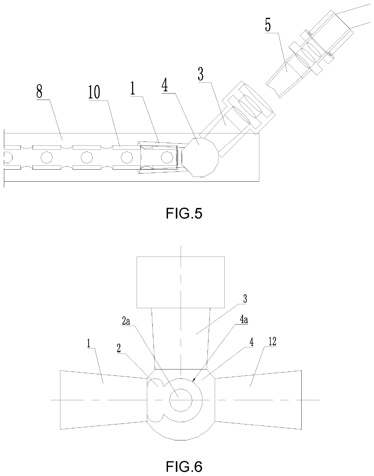
[0055]As shown in FIG. 6, at least one third pipe joint 12 is further integrally connected to the ball shell 4, the third pipe joint 12 is provided with a third through hole (not shown) penetrating through the two ends, and the inner cavity of the ball shell 4 is communicated with the third through hole. Preferably, the structure of the third pipe joint 12 is the same as the structure of the first pipe joint 1, the center line of the third pipe joint 12 third through hole is located on the same straight line with the center line of the first through hole 1a of the first pipe joint 1, and the center line of the second pipe joint 3 second through hole 3a is perpendicular to the center line of the first through hole 1a and the center line of the third through hole. Other structures of the embodiment are the same as that of the first embodiment, and are not described in detail herein. As shown in FIG. 7, the third tube connector 12 can be used for being in butt joint with th...

Example

Embodiment 3

[0056]As shown in FIG. 8, the embodiment provides a wound protection dressing, comprising the connecting device for wound protection dressing according to the first embodiment or the second embodiment, further comprising a rinsing sponge 9 and a drainage sponge 8, a drainage tube 10 is inserted into the drainage sponge 8, the drainage tube 10 is connected with one end, far away from the ball head 2, of the first tube joint 1, the end, far away from the ball shell 4, of the second tube joint 3 is exposed out of the wound protection dressing, and the fourth tube joint 5 is located outside the wound protection dressing. A flushing pipe 11 is inserted into the flushing sponge 9.

[0057]As shown in FIG. 8, FIG. 9 and FIG. 10, the embodiment further comprises a fifth pipe joint 6, the fifth pipe joint 6 comprises two inner joints 611 located on the same straight line in the center line, each inner joint 611 is in a conical shape with an inner small outer part, and the inner join...


PUM


Abstract

A connecting device for a wound protection dressing, and a wound protection dressing. The connecting device comprises a first tube connector (1) and a second tube connector (3); the first tube connector (1) and the second tube connector (3) are respectively provided with a first through hole (1a) and a second through hole (3a) that run through the respective ends of the first tube connector (1) and the second tube connector (3); a hollow ball head (2) is integrally formed on one end of the first tube connector (1); the inner cavity of the ball head (2) are in communication with the first through hole (1a); at least one via hole (2a) is provided on the ball head (2); a ball shell (4) adapted to the ball head (2) is integrally formed on one end of the second tube connector (3); the inner cavity of the ball shell (4) is in communication with the second through hole (3a); a snap-fit hole (4a) is provided on the ball shell (4); the snap-fit hole (4a) has at least one circular fastening hole (4a1); the ball head (2) is snap-fit in the ball shell (4); the end of the first tube connector (1) close to the ball head (2) is fastened in one of the fastening hole (4a1) of the snap-fit hole (4a). Thus, the connecting device for a wound protection dressing and the wound protection dressing which avoid pressing the skin and wound surface, allow the liquid to smoothly flow out, and facilitate flexible connection of the tube line are provided.

Description

BACKGROUND OF THE INVENTION[0001]The invention belongs to the field of medical health, and particularly relates to a connecting device for wound dressing and a wound dressing.[0002]In the prior art, a series of wound treatment and wound protection devices are designed by the inventor, and application of the wound wound treatment device is as follows: the application number of the wound wound treatment device is 201110240452.3, a flushing-drainage type wound wound protection device (application number 20122013474.5), a directional irrigation type wound wound protection device (application number 201220134776.9), an independent irrigation-drainage function module wound repair device (application number 20123090002.6), and an active flushing type negative pressure drainage wound protection device (the application number is 20131200447X). The wound wound treatment and wound protection device for manufacturing the sponge structure dressing with the drainage tube and the flushing tube has...

Claims


Application Information

Patent Timeline
IPC IPC(8): A61M39/10A61M1/00A61F13/00
CPCA61M1/0088A61F13/00068A61M1/0058A61M39/1055A61M2039/1027A61M1/86A61M1/85A61M1/912A61M1/92
Inventor WAN, MIANSHUI
Owner WAN MIANSHUI
Why Eureka
Try Eureka