Driving apparatus and driving signal generating method thereof

a technology of driving apparatus and driving signal, which is applied in the direction of static indicating devices, instruments, cathode-ray tube indicators, etc., can solve the problems of signal attenuation that may occur on the signal transmission path for transmitting display data in the display, and achieve the effect of improving the transmission quality of differential signal pairs

Active Publication Date: 2020-07-23
AU OPTRONICS CORP
View PDF0 Cites 1 Cited by
  • Summary
  • Abstract
  • Description
  • Claims
  • Application Information

AI Technical Summary

Benefits of technology

[0005]The present disclosure provides a driving apparatus and a driving signal generating method for improving transmission quality of a differential signal pair.
[0008]Based on the above, the present disclosure provides a switch connected in series between the first data line and the second data line transmitting the differential signal pair, and the switch is turned on or cut off according to an eye diagram detection result of the differential signal pair. Moreover, the present disclosure defines three time periods through the bi-direction lock signal, and configured to set the setting parameters of the output differential voltage, the pre-emphasis circuit, and the equalizer to actively adjust the transmission properties of the differential signal pair, thereby improving the reliability of signal transmission.

Problems solved by technology

As the size and resolution of the display panel increase, the signal attenuation that may occur on the signal transmission path for transmitting display data in the display becomes more serious.
It is an important issue for practitioners of the field to find out the optimal setting parameters corresponding to various drivers and timing controllers.

Method used


Image

  • Driving apparatus and driving signal generating method thereof
  • Driving apparatus and driving signal generating method thereof
  • Driving apparatus and driving signal generating method thereof

Examples


Embodiment Construction

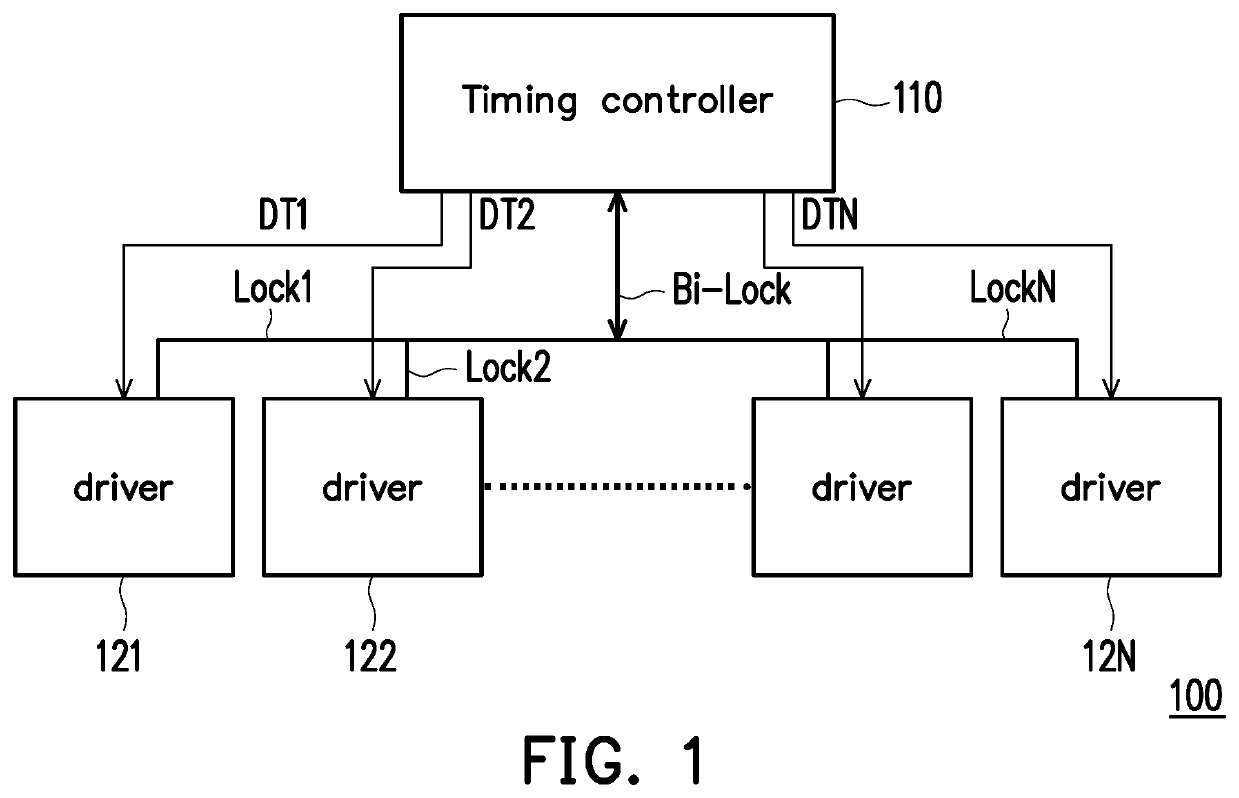
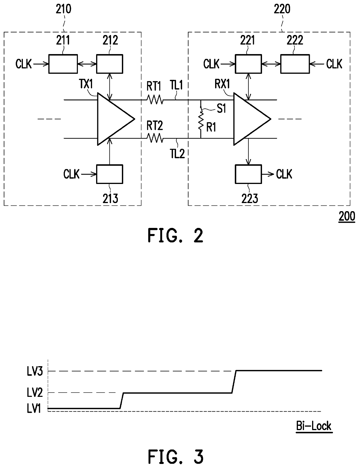
[0018]Please refer to FIG. 1. FIG. 1 is a schematic diagram of a driving apparatus according to an embodiment of the disclosure. A driving apparatus 100 is adapted for a display, and the driving apparatus 100 includes a timing controller 110 and one or more drivers 121˜12N. The timing controller 110 provides an output differential voltage and has a pre-emphasis circuit. The timing controller 110 is coupled to the drivers 121˜12N, receives the lock signals Lock1˜LockN respectively generated by the drivers 121˜12N, and generates a bi-direction lock signal Bi-Lock according to the lock signals Lock1˜LockN. The timing controller 110 transmits the differential signal pairs DT1˜DTN to the drivers 121˜12N, respectively. Please refer to FIG. 1 and FIG. 2, wherein FIG. 2 is a block diagram showing the circuit structure of a driving apparatus according to an embodiment of the disclosure.

[0019]In FIG. 2, a driving apparatus 200 includes a timing controller 210, a driver 220, a switch S1, and a...


PUM


Abstract

A driving apparatus and a driving signal generating method are provided. The driving apparatus includes a timing controller, a driver, a switch and a resistor. The timing controller generates a bi-direction lock signal. The driver receives a differential signal pair. The switch is turned on or cut off according to an eye diagram detection result of the differential signal pair. According to the bi-direction lock signal, the timing controller and the driver are used to: operate a first clock and data recovery (CDR) operation on the differential signal pair during a first time period; set setting parameters of an output differential voltage, a pre-emphasis circuit and an equalizer according to the eye diagram detection result and an on / off state of the switch, and perform a second CDR operation during a second time period; and drive a display according to the differential signal pair during a third time period.

Description

CROSS-REFERENCE TO RELATED APPLICATION[0001]This application claims the priority benefit of Taiwan application serial no. 108102276, filed on Jan. 21, 2019. The entirety of the above-mentioned patent application is hereby incorporated by reference herein and made a part of this specification.BACKGROUNDTechnical Field[0002]The present disclosure relates to a driving apparatus and a driving signal generating method, and more particularly to a driving apparatus and a driving signal generating method for a display.Description of Related Art[0003]As the size and resolution of the display panel increase, the signal attenuation that may occur on the signal transmission path for transmitting display data in the display becomes more serious. In the known technologies, in order to overcome the influence caused by signal attenuation, the timing controller terminal adopts an output differential voltage (VOD) with an increased driving capability and a pre-emphasis (PEMP) circuit, and the driver ...

Claims


Application Information

Patent Timeline
Patent Type & Authority Applications(United States)
IPC IPC(8): G09G5/00G09G5/18
CPCG09G5/008G09G2370/08G09G5/18G09G3/20G09G2320/0693G09G2310/0221G09G2360/04G09G2320/0204G09G2330/12G09G2310/0291
Inventor HUANG, SHENG-YAOWANG, HUNG-CHICHEN, YA-FANG
Owner AU OPTRONICS CORP
Why Eureka
Try Eureka