Gravity Fed Shaving Lather Generating And Dispensing System And Method Of Operation Thereof

Inactive Publication Date: 2020-08-06
CWIOK CARL F
View PDF0 Cites 1 Cited by
  • Summary
  • Abstract
  • Description
  • Claims
  • Application Information

AI Technical Summary

Benefits of technology

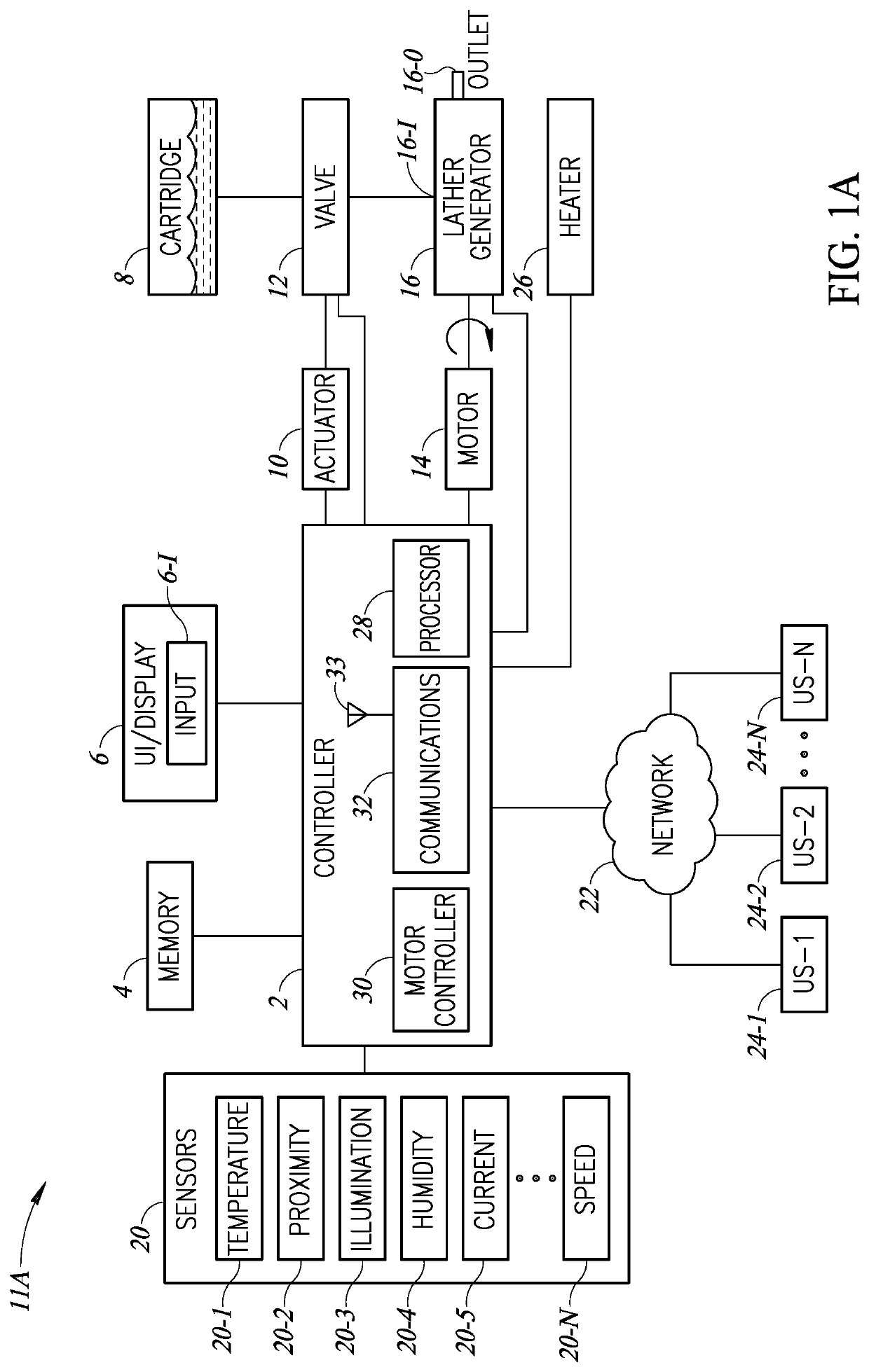
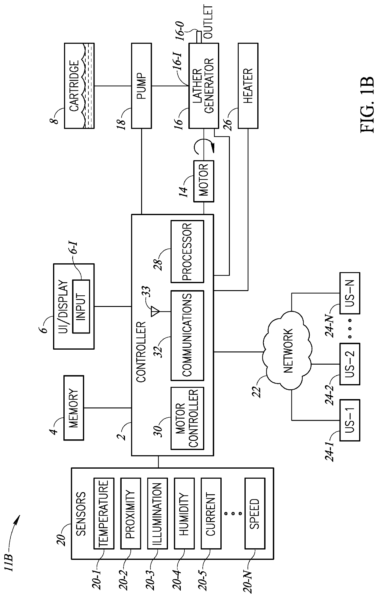
The patent text describes systems, devices, methods, user interfaces, arrangements, computer programs, processes, and so on that address and overcome problems in prior art systems. One technical effect of the invention is a gravity fed shaving lather generator apparatus that includes a lather generator, a motor, and a cylindrical lather generating screw (LGS) that can generate lather from a fluid mixture and output it through a second opening in the lather generator. Another technical effect is a lather generating device that includes a body and a lather generating screw, a controller that can activate a heater, and a heater that can heat the lather generator. A further technical effect is a lather generating device where the controller can engage with the heater when the heater mode is active.

Problems solved by technology

Unfortunately, the shave lather produced using this method may be inferior to that produced by other types of dispensers such as the screw-type dispenser and may include undesirable chemicals to aid in the conversion to a lather.
Unfortunately, this method also produces a shave lather which is inferior to that generated by screw-type lather machines.
Unfortunately, these machines are bulky, difficult to clean, and require frequent maintenance.
For example, individual portions such as reservoirs, etc. of these machines cannot be easily removed for service and / or cleaning.
Further, conventional screw-type lather machines cannot readily dispense different types of lather (e.g., lather of different types, scents, etc.) without emptying the reservoir.

Method used


Image

  • Gravity Fed Shaving Lather Generating And Dispensing System And Method Of Operation Thereof
  • Gravity Fed Shaving Lather Generating And Dispensing System And Method Of Operation Thereof
  • Gravity Fed Shaving Lather Generating And Dispensing System And Method Of Operation Thereof

Examples


Embodiment Construction

[0094]In the following detailed description, numerous specific details are set forth in order to provide a thorough understanding of the invention. It will be understood by those skilled in the art, however, that the present invention may be practiced without these specific details. In other instances, well-known methods, procedures, and components have not been described in detail so as not to obscure the present invention.

[0095]Among those benefits and improvements that have been disclosed, other objects and advantages of this invention will become apparent from the following description taken in conjunction with the accompanying figures. Detailed embodiments of the present invention are disclosed herein; however, it is to be understood that the disclosed embodiments are merely illustrative of the invention that may be embodied in various forms. In addition, each of the examples given in connection with the various embodiments of the invention which are intended to be illustrative...


PUM


Abstract

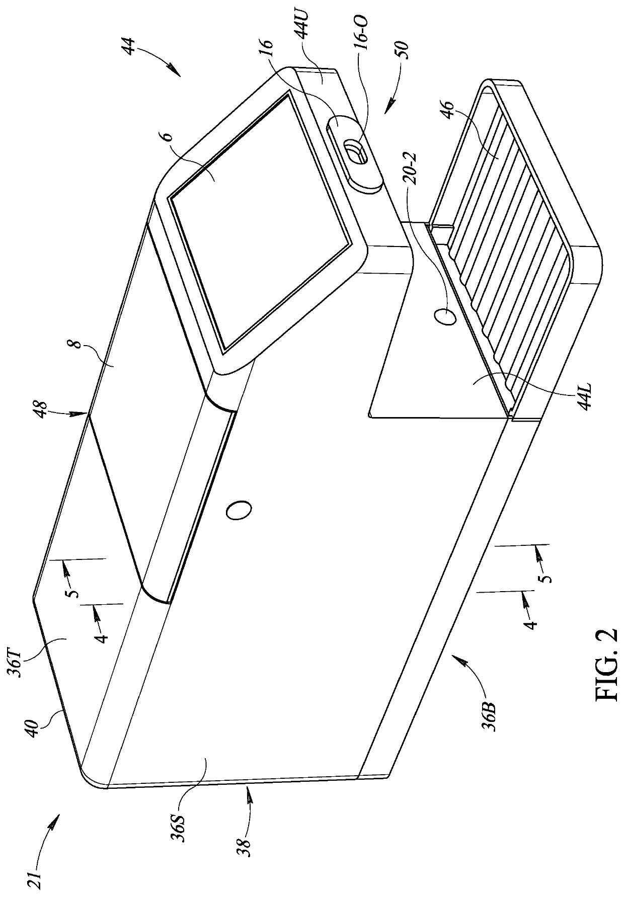
A novel and useful gravity fed shaving lather generator apparatus incorporating a body having a cavity and an inlet port, a removable mixture cartridge comprising a reservoir for containing a fluid, an outlet port extension coupled to the reservoir and configured to be releasably coupled to the inlet port, and a first valve for selectively controlling flow of the fluid from the outlet port extension. The lather generator is situated within the cavity of the body and defines a cylindrical cavity with first and second openings. A cylindrical lather generating screw (LGS) is situated within the cylindrical cavity and configured to generate a lather from the fluid. A motor coupled to the LGS is configured to rotate the LGS within the cylindrical cavity of the lather generator to drive the LGS to output the generated lather at the second opening.

Description

FIELD OF THE DISCLOSURE[0001]The present system relates to a lathering system which can form and output a warm lather suitable for shaving and, more particularly, to a lathering system with an interchangeable lather solution cartridge and a system of operation thereof.BACKGROUND OF THE INVENTION[0002]Heated lather dispensers typically include aerosol-type, pump-type, and screw-type dispensers. The aerosol-type lather dispensers rely upon a compressed lather solution which expands upon being released to atmospheric pressure to form a lather suitable for shaving. Unfortunately, the shave lather produced using this method may be inferior to that produced by other types of dispensers such as the screw-type dispenser and may include undesirable chemicals to aid in the conversion to a lather. With regard to pump-type dispensers, these dispensers rely upon piston type pumps to force a lather solution through a screen to produce a lather suitable for shaving. Unfortunately, this method also...

Claims


Application Information

Patent Timeline
IPC IPC(8): B65D83/72
CPCB65D83/72A45D27/06B05B7/0018B05B12/12B05B12/122
Inventor CWIOK, CARL F.
Owner CWIOK CARL F
Why Eureka
Try Eureka