
Flexible display device

a display device and flexible technology, applied in the direction of identification means, electrical apparatus casings/cabinets/drawers, casings with display/control units, etc., can solve the problems of limitation in extending the screen, the inability to implement a structure, and the inability to apply a large screen to the electronic device of a folding structure. achieve the effect of smooth support and prevent unnecessary load

Active Publication Date: 2020-08-06
LG ELECTRONICS INC
View PDF0 Cites 28 Cited by
  • Summary
  • Abstract
  • Description
  • Claims
  • Application Information

AI Technical Summary

Benefits of technology

The patent allows for the creation of a flexible display unit that can be folded, unfolded, and rolled up for use in a mobile phone, note, or tablet. The user can also smoothly operate the display by moving the rear plate, which prevents unnecessary pressure and damage to the display. The interkinking structure of the device allows for seamless movement between the different states, providing a more compact and user-friendly experience.

Problems solved by technology

Since the conventional display has no folding structure, it was impossible to implement a structure to arrange a display on two bodies connected to each other in a foldable manner.
Therefore, it was impossible to apply a large screen to an electronic device of a folding structure.
In a flexible display device, even if a flexible display is transformable into a folding state and an unfolding state by using a hinge unit, there is a limitation in extending a screen.
Further, when the folding state is converted into the unfolding state or vice versa, an unnecessary load may be applied to the flexible display, or a folding in a reverse direction may be performed to cause inconvenience to a user.

Method used


Image

  • Flexible display device
  • Flexible display device
  • Flexible display device

Examples


Embodiment Construction

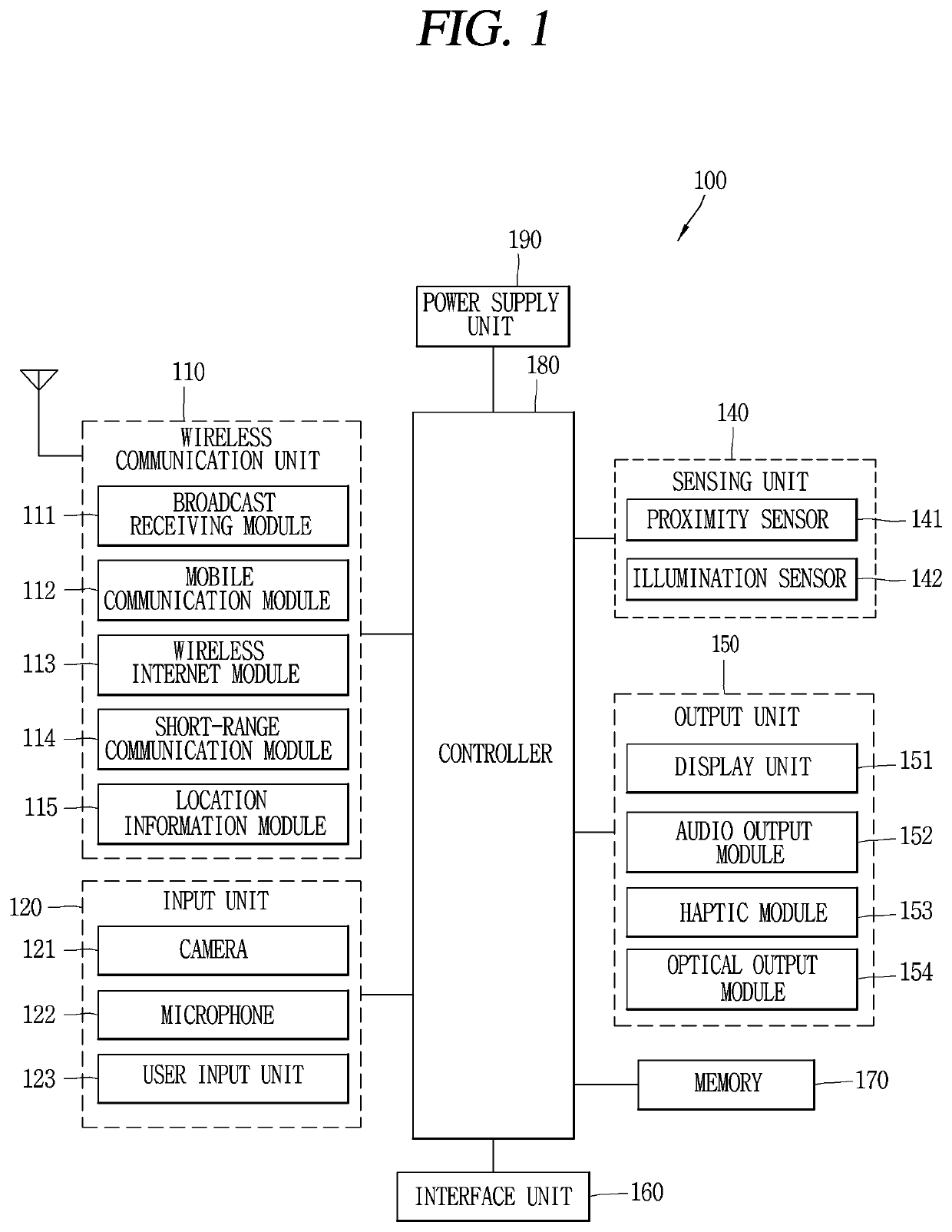
[0031]Description will now be given in detail according to exemplary embodiments disclosed herein, with reference to the accompanying drawings. For the sake of brief description with reference to the drawings, the same or equivalent components may be provided with the same or similar reference numbers, and description thereof will not be repeated. In general, a suffix such as “module” and “unit” may be used to refer to elements or components. Use of such a suffix herein is merely intended to facilitate description of the specification, and the suffix itself is not intended to give any special meaning or function. The accompanying drawings are used to help easily understand the technical idea of the present disclosure and it should be understood that the idea of the present disclosure is not limited by the accompanying drawings. The idea of the present disclosure should be construed to extend to any alterations, equivalents and substitutes besides the accompanying drawings.

[0032]Alth...


PUM


Abstract

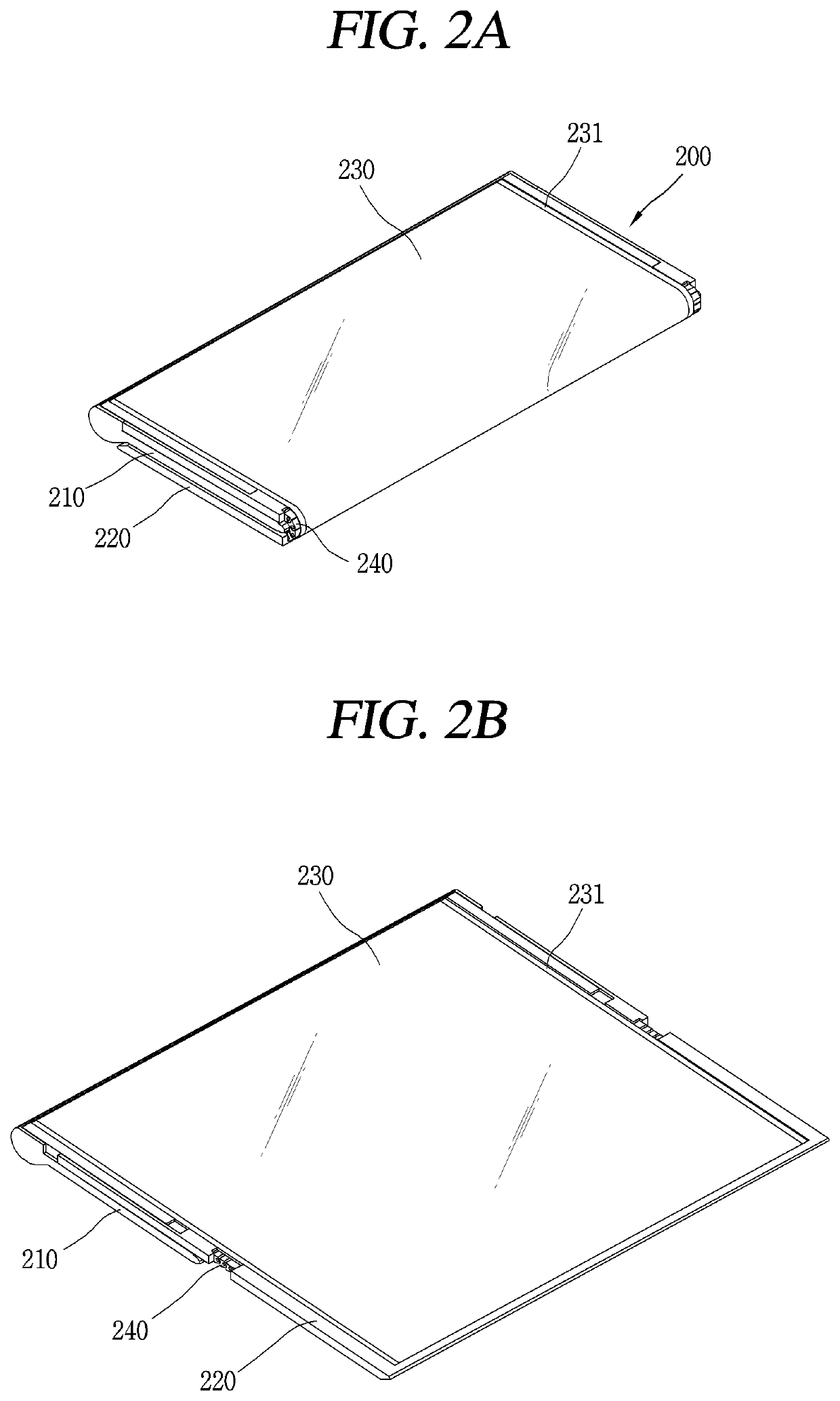
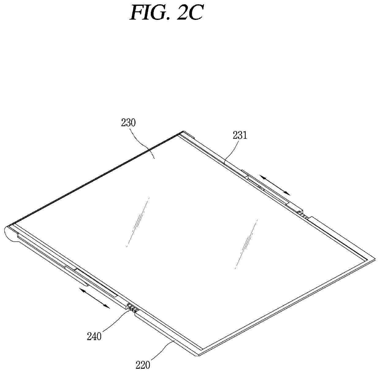
A flexible display device including a first body; a second body; a flexible display unit arranged on a front surface of the first and second bodies; and a rear plate coupled to a rear surface of the flexible display unit, and configured to be transformed together with the flexible display unit. Further, in a folded state of the flexible display unit, the second body covers a rear surface of the first body, a first part of the rear plate is wound around a bearing portion in the first body together with a first part of the flexible display unit, and a second part of the rear plate is coupled to a second part of the flexible display unit exposed to the outside; in an unfolded state of the flexible display unit, the first body and the second body are arranged in parallel; and in an extending state of the flexible display unit from the unfolded state, the first body is extended and the first part of the rear plate is unwound from the bearing portion together with the flexible display unit to increase an exposed region of the flexible display unit.

Description

CROSS-REFERENCE TO RELATED APPLICATIONS[0001]Pursuant to 35 U.S.C. § 119(e), this application claims the benefit of an earlier filing date and priority to U.S. Provisional Application No. 62 / 799,705 filed on Jan. 31, 2019, and under 35 U.S.C. § 119(a) to Korean Application Nos. 10-2019-0049318 filed in the Republic of Korea on Apr. 26, 2019 and 10-2019-0039173 filed in the Republic of Korea on Apr. 3, 2019, all of which are hereby expressly incorporated by reference into the present application.BACKGROUND OF THE INVENTION1. Field of the Invention[0002]The present disclosure relates to a flexible display device, and particularly, to a flexible display device having a flexible display unit which is transformable by an external force.2. Discussion of the Related Art[0003]A portable electronic device (hereinafter, a mobile terminal) such as a communication terminal, a multimedia device, a portable computer, a game machine and a capturing device is provided with a display for displaying ...

Claims


Application Information

Patent Timeline
Patent Type & Authority Applications(United States)
IPC IPC(8): H05K5/02H05K5/00
CPCH05K5/0226H05K5/0017G06F1/1652G09F9/301G06F1/1681G06F1/1616
Inventor CHA, YOUNGDO
Owner LG ELECTRONICS INC
Learn More