Portable printer

Active Publication Date: 2020-08-13
J STEPHEN LAB LTD
View PDF0 Cites 0 Cited by
  • Summary
  • Abstract
  • Description
  • Claims
  • Application Information

AI Technical Summary

Benefits of technology

[0024]According to the present invention, it is possible to easily and quickly open the cover part without a separate process by the operation of the operating part in another direction while cutting clearly the paper

Problems solved by technology

In addition, when the continuous paper fed inside the printer is used up, replacement of the paper is required.
However, in the case of a conventional portable printer using an auto cutting scheme, a power source for automatic cutting is required.
In addition, in such a case, required operating motor and circuit configurations are required to cause a disadvantage, such as the complexity of the product configuration or the rise in product prices.
Further, the scheme has a disadvantage that since a battery is used as a power source of the

Method used


Image

  • Portable printer
  • Portable printer
  • Portable printer

Examples


first embodiment

[0038]A first embodiment of the present invention will be described with reference to FIGS. 1 to 3.

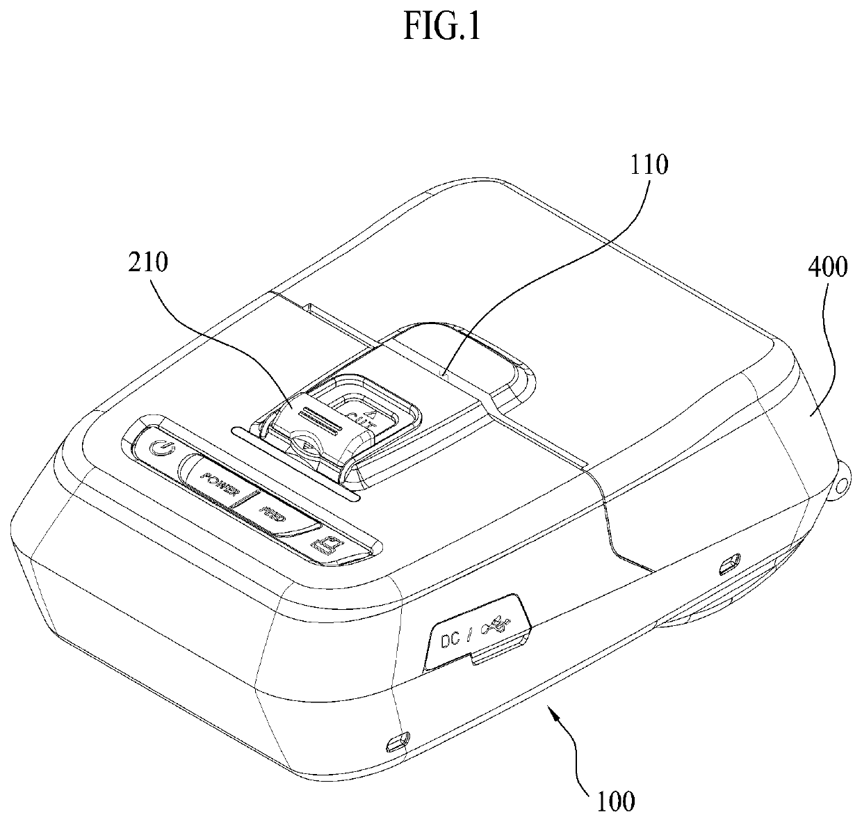
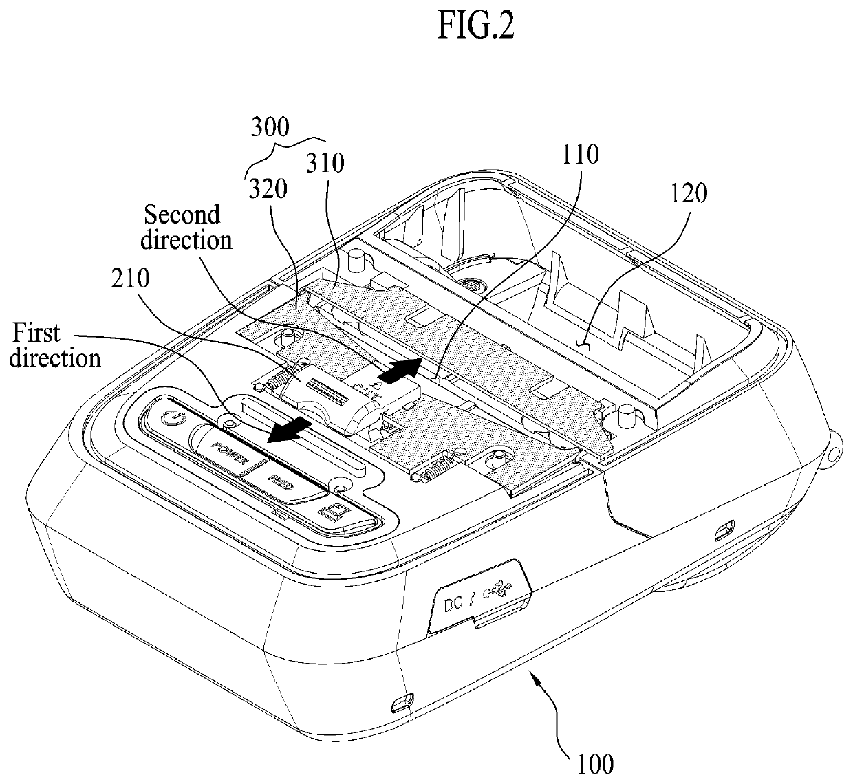
[0039]A portable printer of the present invention includes a main body part 100, a cover part 400, an operating part 200, and a cutting part 300.

[0040]The main body part 100 is a portion constituting the main body of the portable printer, and provided with a paper feeding port 120 and a paper discharge port 110.

[0041]The paper feeding port 120 is positioned inside the main body part 100 as a portion for storing the continuous paper 10 printed and output by the operation of the printer.

[0042]The paper discharge port 110 refers to a portion in which the continuous paper 10 is printed and output to the outside of the portable printer.

[0043]The cover part 400 is formed to cover the paper feeding port 120 of the main body part 100.

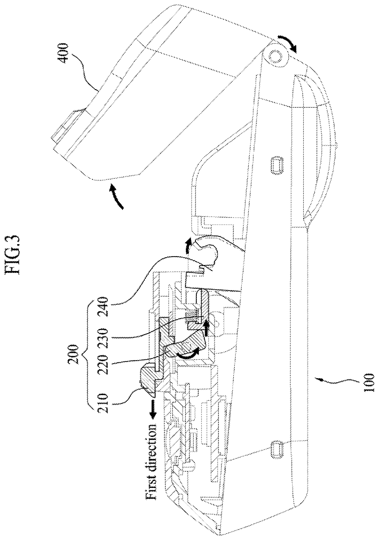
[0044]The cover part 400 is coupled to the main body part 100 so as to be opened and closed, and the cover part 400 is opened when the operating part 200 slides. ...

second embodiment

[0071]A second embodiment of the present invention will be described in detail with reference to FIG. 4.

[0072]The contents omitted in the present embodiment are the same as or similar to the contents mentioned in the first embodiment of the present invention, and those skilled in the art can easily understand and implement the invention by only those described in detail below.

[0073]According to the present embodiment, the operating part 200 may be provided with the operating member 210, the rotating member 220, and the frame 240.

[0074]The operating member 210 is provided to be adjacent to the paper discharge port 110 and is provided to slide in a first or second direction by receiving an external force.

[0075]The rotating member 220 in the present embodiment may be provided to be rotatable in a height direction of the main body part 100 at a lower portion of the main body part 100 on which a second cutter member 320 to be described below is mounted.

[0076]When the operating member210 ...

third embodiment

[0078]A third embodiment of the present invention will be described in detail with reference to FIG. 5.

[0079]The contents omitted in the present embodiment are the same as or similar to the contents mentioned in the first embodiment of the present invention, and those skilled in the art can easily understand and implement the invention by only those described in detail below.

[0080]According to the present embodiment, the operating part 200 may be provided with the operating member 210 and the frame 240.

[0081]The operating member 210 is provided to be adjacent to the paper discharge port 110 and is provided to slide in a first or second direction by receiving an external force.

[0082]The frame 240 in the present embodiment may be elongated so that a part of the frame 240 comes into contact with a portion protruding to the lower portion of the operating member 210. That is, the frame 240 has a shape that is opened downward.

[0083]Accordingly, a force is transmitted to the frame 240 when...


PUM


Abstract

A portable printer according to the present invention includes: a main body part having a paper feeding port and a paper discharge port; a cover part coupled to the main body part to be opened and closed; a cutting part disposed to be adjacent to the paper discharge port and cutting paper discharged from the paper discharge port; and an operating part sliding in at least two directions by an external force so as to operate the cover part or the cutting part.

Description

BACKGROUND(a) Technical Field[0001]The present invention relates to a portable printer, and more particularly, to a portable printer in which discharged paper is cut by a cutting part provided in the portable printer or a cover part is opened according to the sliding of an operating part.(b) Background Art[0002]In a point of sale system and an automated recognition system, a printer has been used for printing receipts and labels.[0003]The printer used for the above is generally a thermal transfer printer, and is provided with a cutting device for using continuous paper and cutting outputted paper.[0004]In addition, when the continuous paper fed inside the printer is used up, replacement of the paper is required.[0005]However, in the case of a conventional portable printer using an auto cutting scheme, a power source for automatic cutting is required.[0006]In addition, in such a case, required operating motor and circuit configurations are required to cause a disadvantage, such as th...

Claims


Application Information

Patent Timeline
IPC IPC(8): B41J11/70
CPCB41J11/70B41J3/36B41J29/13B26D1/015B26D1/085B26D5/10B41J11/66
Inventor KWON, SUN TAE
Owner J STEPHEN LAB LTD
Why Eureka
Try Eureka