
Surgery assisting apparatus and control method of the same, and surgery assisting system

a technology of surgery assisting and control methods, applied in the field of surgery assisting apparatus and control methods of the same, can solve the problems of inability to accurately sense the approach of the medical instrument to a momentarily changing organ, the damage cannot be treated with technique, and the part of the medical instrument touching and damaging an organ, etc.

Inactive Publication Date: 2020-09-24
A TRACTION INC
View PDF0 Cites 0 Cited by
  • Summary
  • Abstract
  • Description
  • Claims
  • Application Information

AI Technical Summary

Benefits of technology

Enables accurate sensing of medical instrument approaches to objects in the body cavity, preventing contact and ensuring safe operation by controlling the instrument's movement based on real-time distance measurements, thereby enhancing the precision and safety of laparoscopic procedures.

Problems solved by technology

Since the range observable by the endoscope in the body cavity is narrower than the range within which the distal end of the medical instrument operates, there is the possibility that a part of the medical instrument touches and damages an organ or the like outside the field of view of the endoscope.
However, a medical instrument touches an organ in the technique disclosed in Japanese Patent Laid-Open No. 2004-81277, so this technique cannot be used for a fragile organ which is damaged only when touched.
This sometimes makes it impossible to accurately sense approach of the medical instrument to a momentarily changing organ or the like.
However, the measurement range is narrow because the electronic distance meter is installed in the distal end of a medical instrument, and it is impossible to detect interference in a shaft portion (a portion closer to the body wall than the distal end) other than the distal end of the medical instrument.

Method used


Image

  • Surgery assisting apparatus and control method of the same, and surgery assisting system
  • Surgery assisting apparatus and control method of the same, and surgery assisting system
  • Surgery assisting apparatus and control method of the same, and surgery assisting system

Examples


Embodiment Construction

[0026]Exemplary embodiments of the present invention will be explained in detail below with reference to the accompanying drawings.

[0027](Configuration of Surgery Assisting Apparatus)

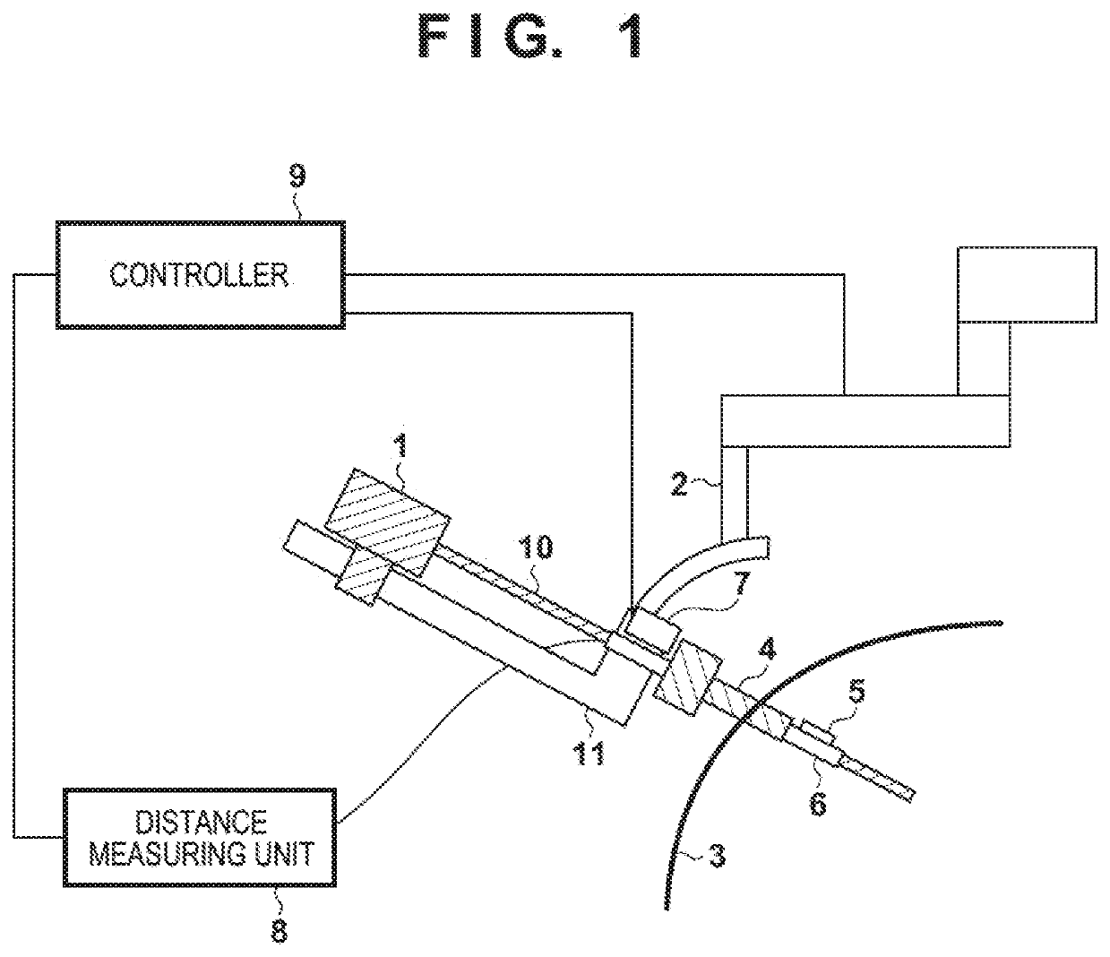
[0028]FIG. 1 is a view showing a functional configuration example of a surgery system including a surgery assisting apparatus according to an embodiment.

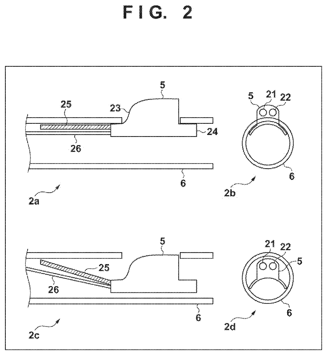
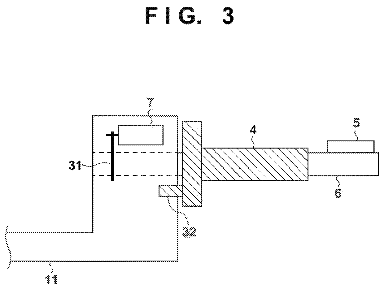
[0029]This surgery system includes a medical instrument 1, a medical instrument driving unit 2, a mantle tube (trocar) 4, an optical part holder 5, a hollow tube 6, a hollow tube driving unit 7, a distance measuring unit 8, and a controller 9. Of these components, the surgery assisting apparatus according to this embodiment includes the optical part holder 5, the hollow tube 6, the hollow tube driving unit 7, the distance measuring unit 8, and the controller 9.

[0030]The medical instrument 1 includes forceps, tweezers, an electric knife, a suction tube, an ultrasonic scalpel, a hemostatic device, a radiofrequency ablation device, an endoscope, a thoracos...


PUM


Abstract

A surgery assisting apparatus comprises: a distance measuring unit configured to measure a distance to an object in a body cavity; a hollow tube including a cylindrical portion to be partially inserted into the body cavity and a portion that performs distance measurement by the distance measuring unit, the hollow tube enabling distance measurement in a given position on a circumference at a predetermined distance from a major axis of the cylindrical portion; and a controller configured to control the position on the circumference around the major axis where the distance measuring unit performs distance measurement, such that approach of a medical instrument inserted into the body cavity to the object is sensed, wherein the controller controls the position on the circumference around the major axis in accordance with an advancing direction of a distal end of the medical instrument.

Description

[0001]This application is a continuation of International Patent Application No. PCT / JP2016 / 085615 filed on Nov. 30, 2016, and claims priority to Japanese Patent Application No. 2016-126708 filed on Jun. 27, 2016, the entire content of both of which is incorporated herein by reference.BACKGROUND OF THE INVENTIONField of the Invention[0002]The present invention relates to a surgery assisting apparatus and a control method of the same, and a surgery assisting system.Description of the Related Art[0003]Laparoscopic surgery is conventionally performed by forming a small-diameter hole in the abdominal wall and inserting a medical instrument such as an endoscope or therapeutic device into the body cavity from the small-diameter hole. Since the range observable by the endoscope in the body cavity is narrower than the range within which the distal end of the medical instrument operates, there is the possibility that a part of the medical instrument touches and damages an organ or the like o...

Claims


Application Information

Patent Timeline
Patent Type & Authority Applications(United States)
IPC IPC(8): A61B34/20
CPCA61B2034/2055A61B34/20A61B2034/2057A61B1/00006A61B1/00133A61B1/00149A61B34/30A61B90/06A61B2090/062A61B2090/08021G02B23/2415A61B1/00147A61B1/3132A61B17/34A61B2034/2059A61B2090/061A61B2090/306A61B2090/309A61B2090/371A61B1/00097
Inventor ANDO, TAKEHIROMIYAMOTO, HIROYUKI
Owner A TRACTION INC
Learn More