Sacroiliac joint fusion implants and methods

a technology of fusion implants and sacroiliac joints, applied in the field of fusion surgery, can solve the problems of insufficient posterior approach, pelvic, groin, hip pain, pelvic pain, etc., and achieve the effect of facilitating bone growth and promoting bone growth

Pending Publication Date: 2020-09-24
MULLIN BRAD
View PDF5 Cites 1 Cited by
  • Summary
  • Abstract
  • Description
  • Claims
  • Application Information

AI Technical Summary

Benefits of technology

[0008]Presently disclosed is a joint implant. In an embodiment, a joint implant includes a porous body configured to promote bone growth, the body having a porous body with a first face, a second face, and a window extending between the first and second faces. The window is configured to hold a graft material that facilitates bone growth when the implant is maintained in compression with the first face contacting the sacrum and the second face contacting the ilium.

Problems solved by technology

Dysfunction in the SI joint can produce significant lower back pain, as well as pelvic, groin, and hip pain.
This dysfunction can be the result of too much motion, too little motion, or inflammation of the joint.
This torque T acting on the SI joint 100 may result in pain if there is dysfunction in the SI joint 100.
Thus, physicians performing SI joint fusion tend to be more familiar with posterior approaches than lateral approaches, however, the posterior approach is not presently utilized during SI joint fusion operations.
Also, performing SI joint fusion via the lateral approach may not be performed simultaneous with lumbar or spinal operations using posterior approaches.
In addition, many current SI joint fusion techniques do not incorporate bone grafts to strengthen the SI joint 100 when fused, but instead only rely on the strength of the dowel rods and pins to secure the SI joint 100.
These dowel rods and pins deteriorate over time and ultimately fail, unless there is a bony fusion, thereby subjecting patients to additional surgery.

Method used


Image

  • Sacroiliac joint fusion implants and methods
  • Sacroiliac joint fusion implants and methods
  • Sacroiliac joint fusion implants and methods

Examples


Embodiment Construction

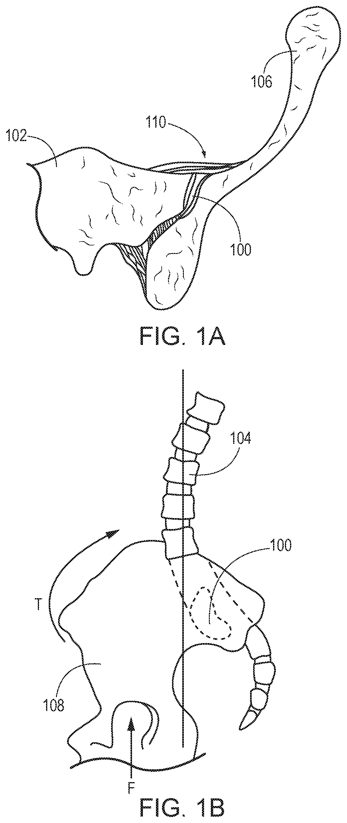
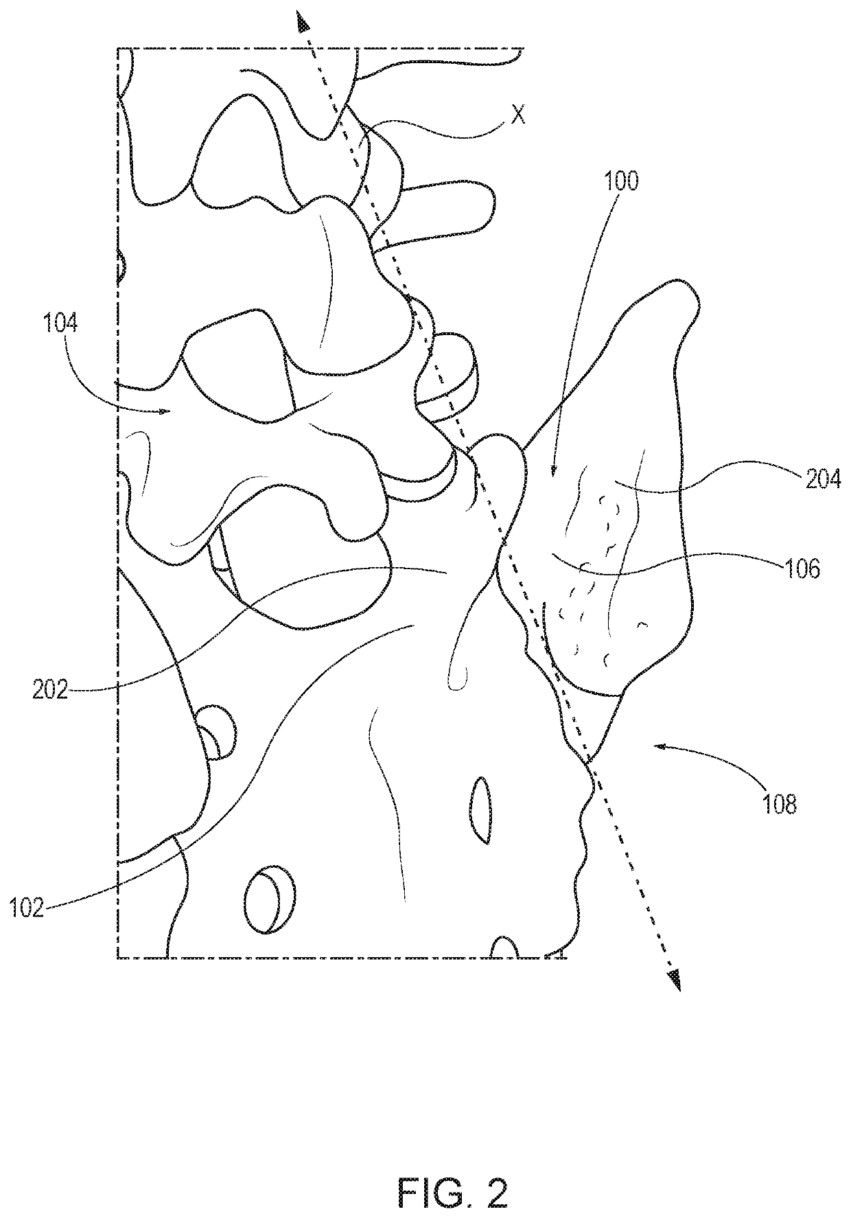
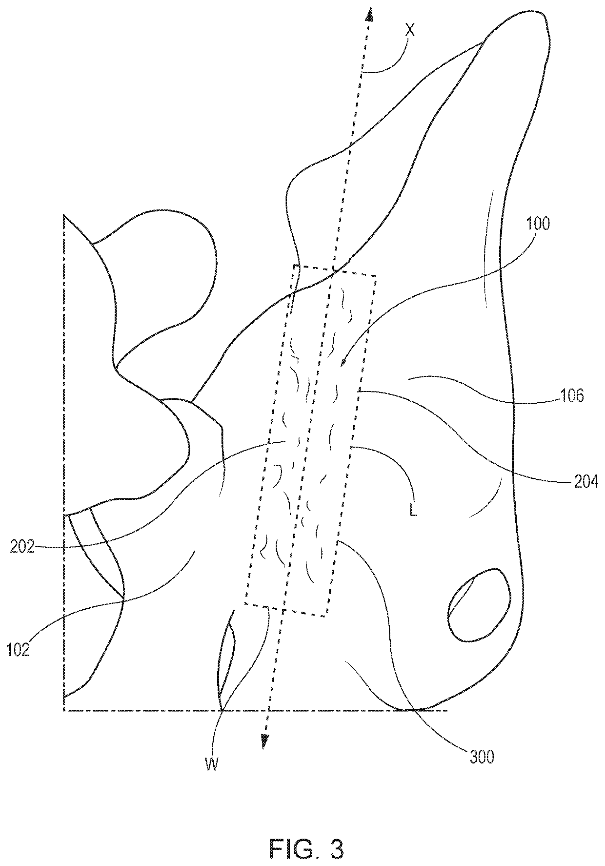
[0026]The present disclosure relates in general to SI joint fusions and, more particularly, to implants and methods for posterior SI joint fusion.

[0027]The embodiments described herein provide methods of performing SI joint fusions via posterior approaches (i.e., posterior SI joint fusions). The embodiments described herein also provide reaming guides utilizable in posterior SI joint fusions for defining the tool path and limiting the depth of cut as needed for a particular physiology. In some embodiments, the reaming guides are boxes oriented parallel to the SI joint. Other embodiments described herein provide a fusion plate utilizable in a posterior SI joint fusion and having a window for holding graft material that helps bone grow across the porous fusion plate through the window. In some embodiments, the fusion plate is made from a porous material that helps bone grow into and across the fusion plate, which thereby facilitates bone growth through the plate and bone fusion within...


PUM


Abstract

Presently disclosed is a sacroiliac joint implant. In an embodiment, a sacroiliac joint implant includes a porous body configured to promote bone growth. The porous body may have a window that is configured to hold a graft material. The porous body may also include a first face and second face configured to contact the sacrum and the ilium of the sacroiliac joint when the implant is maintained in compression within the sacroiliac joint.

Description

CROSS-REFERENCE TO RELATED APPLICATION[0001]This application claims priority to and the benefit of U.S. Provisional Patent Application No. 62 / 820,345, filed Mar. 19, 2019, which is incorporated by reference herein in its entirety.BACKGROUND OF THE INVENTION[0002]The present disclosure relates to fusion surgery, and more particularly, to sacroiliac joint fusion.[0003]The sacroiliac joint (the “SI joint”) is a low-motion joint that connects the hip bones to either side of the sacrum, acting primarily as a shock-absorber between the lower body and torso. Dysfunction in the SI joint can produce significant lower back pain, as well as pelvic, groin, and hip pain. This dysfunction can be the result of too much motion, too little motion, or inflammation of the joint.[0004]FIGS. 1A-1B illustrate an SI joint 100, and FIG. 1A is a cross-sectional view of the SI joint 100 from an anterior approach. As shown, the SI joint 100 is located between the sacrum 102 at the base of the spine 104 (see F...

Claims


Application Information

Patent Timeline
Patent Type & Authority Applications(United States)
IPC IPC(8): A61F2/30A61F2/28A61F2/46
CPCA61B17/7011A61F2310/00023A61F2002/30784A61F2002/3093A61F2002/30995A61F2/30988A61F2002/30622A61F2/2846A61F2/30749A61F2/4603A61B17/7055A61B17/1757
Inventor MULLIN, BRAD
Owner MULLIN BRAD
Why Eureka
Try Eureka