Dispensing device suitable for a foamable product
- Summary
- Abstract
- Description
- Claims
- Application Information
AI Technical Summary
Benefits of technology
Problems solved by technology
Method used
Image
Examples
first embodiment
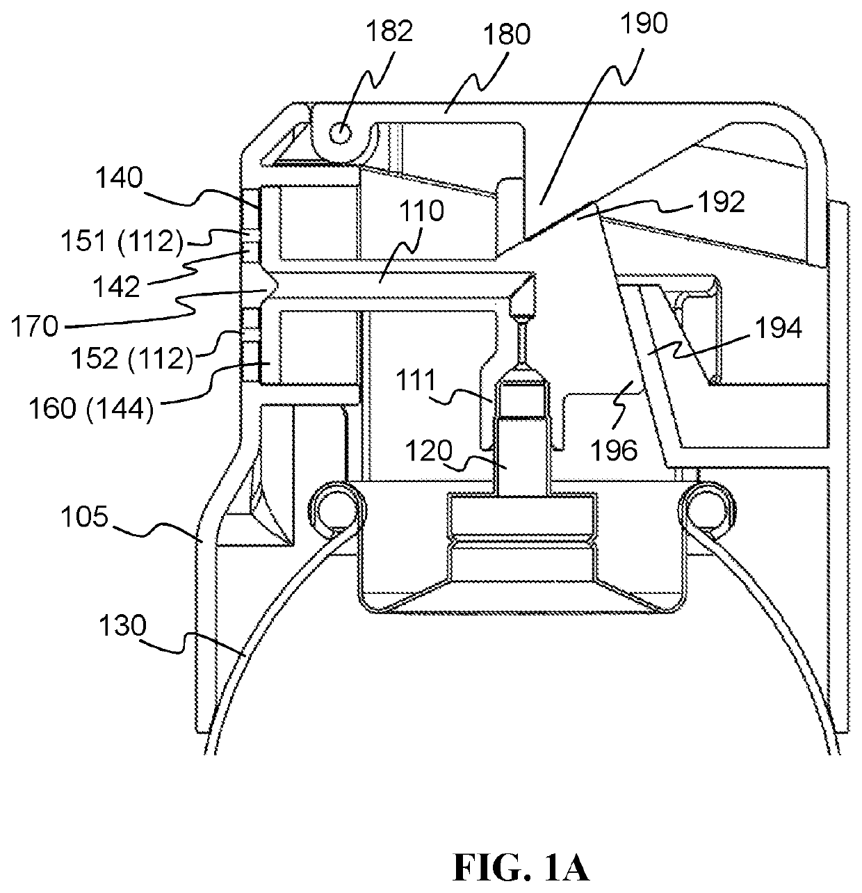
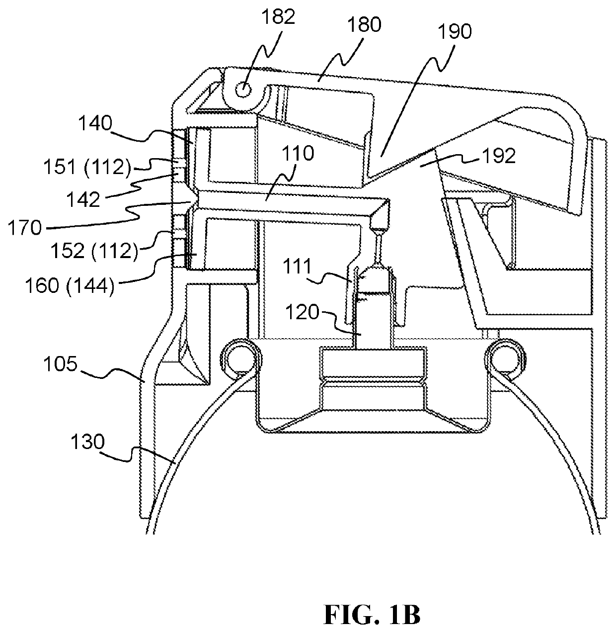
[0087]FIG. 1A is a cross sectional side view showing a dispensing device, suitable for dispensing a foamable product, according to the invention. The drawing shows the dispensing device attached to the top of a container 130, which contains the foamable product.
[0088]The dispensing device comprises a dispensing channel 110, which has an inlet 111 and an outlet 112. The inlet 111 is coupled to and in fluid communication with a valve-element 120 of the container 130. In this embodiment, the valve-element 120 is a valve stem. The outlet 112 is in fluid communication with the exterior of the dispensing device, to allow the foamable product to be dispensed.
[0089]The dispensing channel further comprises a variable-volume cavity 140 at the outlet 112. This cavity 140 is defined by a first component 142 and a second, separate component 144. The cavity 140 is the space between these two components. The second component 144 is able to slide (and tilt) with respect to the first component 142, ...
second embodiment
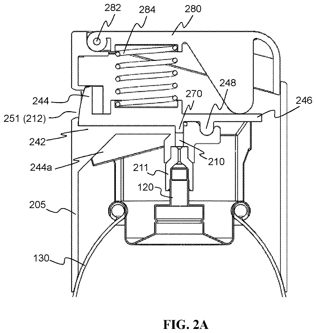
[0105]In the second embodiment, the outlet 212 is defined by a single opening 251 in the outer end of the first component 242. In this example, the opening 251 is circular. The outer end of the second component 244 is shaped into an arc and the inner side of the first component 242 at the outer end (outlet 212) is shaped into a corresponding arc. In this way, the outer end of the second component 244 blocks and closes the opening 251 at the outlet 212 in the first configuration.
[0106]In the second configuration, with the second component 244 rotated away from the first component 242, the first component 242 forms the floor of the variable-volume cavity 240. The second component 244 forms the ceiling of the cavity 240. The sides of the cavity 240 are formed by sidewalls 244a, which are attached to the second component 244 and rotate with it. In this embodiment, the sidewalls 244a are formed integrally with the second component 244. The outer end of the cavity 240, where the outlet 21...
PUM
 Abstract
Description
Claims
Application Information
 - R&D
- Intellectual Property
- Life Sciences
- Materials
- Tech Scout
- Unparalleled Data Quality
- Higher Quality Content
- 60% Fewer Hallucinations
Browse by: Latest US Patents, China's latest patents, Technical Efficacy Thesaurus, Application Domain, Technology Topic, Popular Technical Reports.
© 2025 PatSnap. All rights reserved.Legal|Privacy policy|Modern Slavery Act Transparency Statement|Sitemap|About US| Contact US: help@patsnap.com


