Keyswitch structure

Active Publication Date: 2020-10-15
DARFON ELECTRONICS CORP
View PDF0 Cites 1 Cited by
  • Summary
  • Abstract
  • Description
  • Claims
  • Application Information

AI Technical Summary

Benefits of technology

[0008]Compared with the prior art, the keyswitch structure according to the invention uses an incomplete hole-shaft structure and thereby can maintain the structural strength of the supports. The above pivotal connection of the shaft with the C-shaped shaft hole produces structural elasticity during assembly and restriction in all directions, which can maintain both the structural strength of the pivotal connection and the rotation stability, so as to prevent the supports from permanent deformation or damage during assembly. In the above pivotal connection of the shaft portion with the semi-shaft hole, the projection of the sliding contact surface of the two supports onto a plane perpendicular to the rotation axis can show

Problems solved by technology

For automatic assembly, the above assembly ways make it difficult to adjust processes and design jigs, and even to avoid excessively scraping due to misalignment, which also will affect the yield and production capacity.
During a pressing operation on a keyswitch having the two supports, the engagement of the toothed structures will produce engagement and disengagement of the teeth thereof many times, which increases the instability of the keycap of the keyswitch during the pressing operation.
This structural configuration also will

Method used


Image

  • Keyswitch structure
  • Keyswitch structure
  • Keyswitch structure

Examples


Example

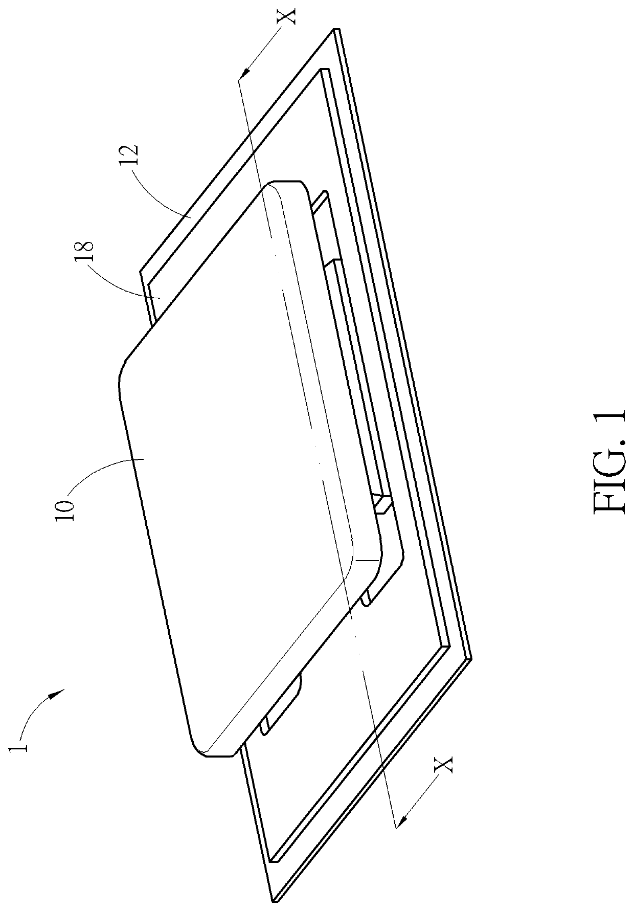
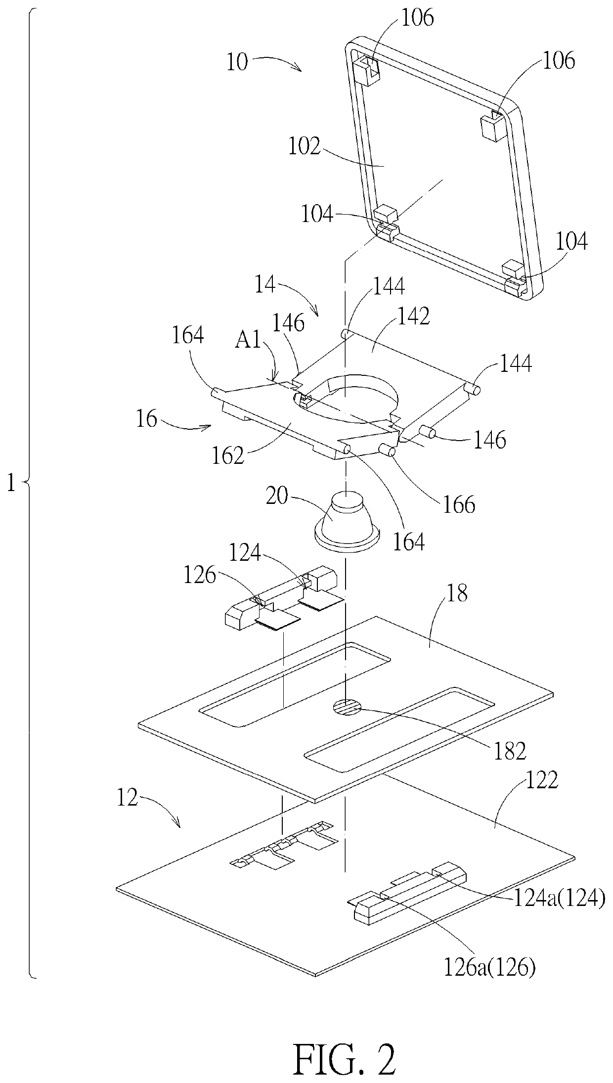
[0020]Please refer to FIG. 1 and FIG. 2. A keyswitch structure 1 according to an embodiment includes a keycap 10, a base 12, a first support 14, a second support 16, a switch circuit board 18, and a resilient restoration part 20. The base 12 is disposed under the keycap 10. The first support 14 and the second support 16 are pivotally connected with each other relative to a rotation axis A1 (indicated by a chain line in FIG. 2) and respectively are connected to and between the keycap 10 and base 12. The switch circuit board 18 is disposed on the base 12. The resilient restoration part 20 is disposed on the switch circuit board 18 corresponding to a switch 182 (indicated by a circle with hatched lines in FIG. 2) of the switch circuit board 18. The keycap 10 can vertically move up and down relative to the base 12 through the first support 14 and the second support 16. When moving downward, the keycap 10 can press the resilient restoration part 20 to trigger the switch 182. In practice,...


PUM


Abstract

A keyswitch structure includes a keycap, a base, and two supports that are pivotally connected to each other and connected to and between the keycap and the base. The keycap can move up and down relative to the base through the two supports. In an embodiment, the two supports are pivotally connected through an engagement of a shaft with a C-shaped shaft hole. In another embodiment, each support is provided in a form of an n-shaped structure and includes a semi-shaft hole and a shaft portion at two ends of the n-shaped structure respectively. The two supports are pivotally connected by the shaft portions rotatably abutting the corresponding semi-shaft holes.

Description

BACKGROUND OF THE INVENTION1. Field of the Invention[0001]The present invention relates to a mechanical keyswitch structure, and more particularly to a mechanical keyswitch structure, of which the keycap is supported by and is movable through two supports.2. Description of the Prior Art[0002]Many mechanical keyswitch structures use a scissors support to support its keycap. The two supports of the scissors support are usually pivotally connected through a complete hole and a complete shaft formed at middle portions of the two supports fitting with each other. The hole-shaft fit can provide good relative rotation stability for the supports. However, if the two supports are pivotally connected through a complete hole-shaft structure, the two supports usually need to be assembled together along the pivot axis, or need to cross at a specific angle so as to be assembled. For automatic assembly, the above assembly ways make it difficult to adjust processes and design jigs, and even to avoi...

Claims


Application Information

Patent Timeline
IPC IPC(8): H01H13/14H01H13/10
CPCH01H13/10H01H13/14H01H3/122H01H3/125
Inventor CHAO, LING-HSI
Owner DARFON ELECTRONICS CORP
Why Eureka
Try Eureka