Flexible vapor chamber

a flexible and vapor chamber technology, applied in the direction of heat exchange apparatus, lighting and heating apparatus, reinforcement means, etc., can solve the problems of damage to electronic components, large heat generation of electronic components within mobile electronic devices, and drawbacks in the structure of heat pipes, so as to achieve effective maintenance of the structural strength of the casing

Inactive Publication Date: 2020-10-15
AURAS TECH
View PDF0 Cites 11 Cited by
  • Summary
  • Abstract
  • Description
  • Claims
  • Application Information

AI Technical Summary

Benefits of technology

[0008]For solving the drawbacks of the conventional technologies, the present invention provides a flexible vapor chamber for an electronic device. The installation of the flexible vapor chamber complies with a shape of the electronic device. Moreover, the structural strength of the casing is effectively maintained to prevent from the collapse of the internal accommodation space.
[0026]From the above descriptions, the flexible vapor chamber includes the support structures to effectively maintain the structural strength of the casing in order to prevent from the collapse of the internal accommodation space. The installation of the flexible vapor chamber complies with a shape of the electronic device. Due to the flexible properties, the installation flexibility of the heat dissipation device is enhanced.

Problems solved by technology

Moreover, as the functions and performance of these mobile electronic devices are gradually enhanced, the electronic components within the mobile electronic devices generate a great deal of heat.
If the heat cannot be effectively dissipated away from the narrow internal space, the elevated temperature may result in damage of the electronic components.
Consequently, it is an important issue to design the heat dissipation mechanism of the mobile electronic device.
However, in case that the internal space of the mobile electronic device is small, the structure of the heat pipe has some drawbacks.
That is, the shape of the heat pipe is not flexible.
However, since the heat conduction area of the vapor chamber is large, some drawbacks occur.
For example, if the structural strength of the casing of the vapor chamber is insufficient, the casing is readily suffered from collapse toward the internal side.

Method used


Image

  • Flexible vapor chamber
  • Flexible vapor chamber
  • Flexible vapor chamber

Examples


first embodiment

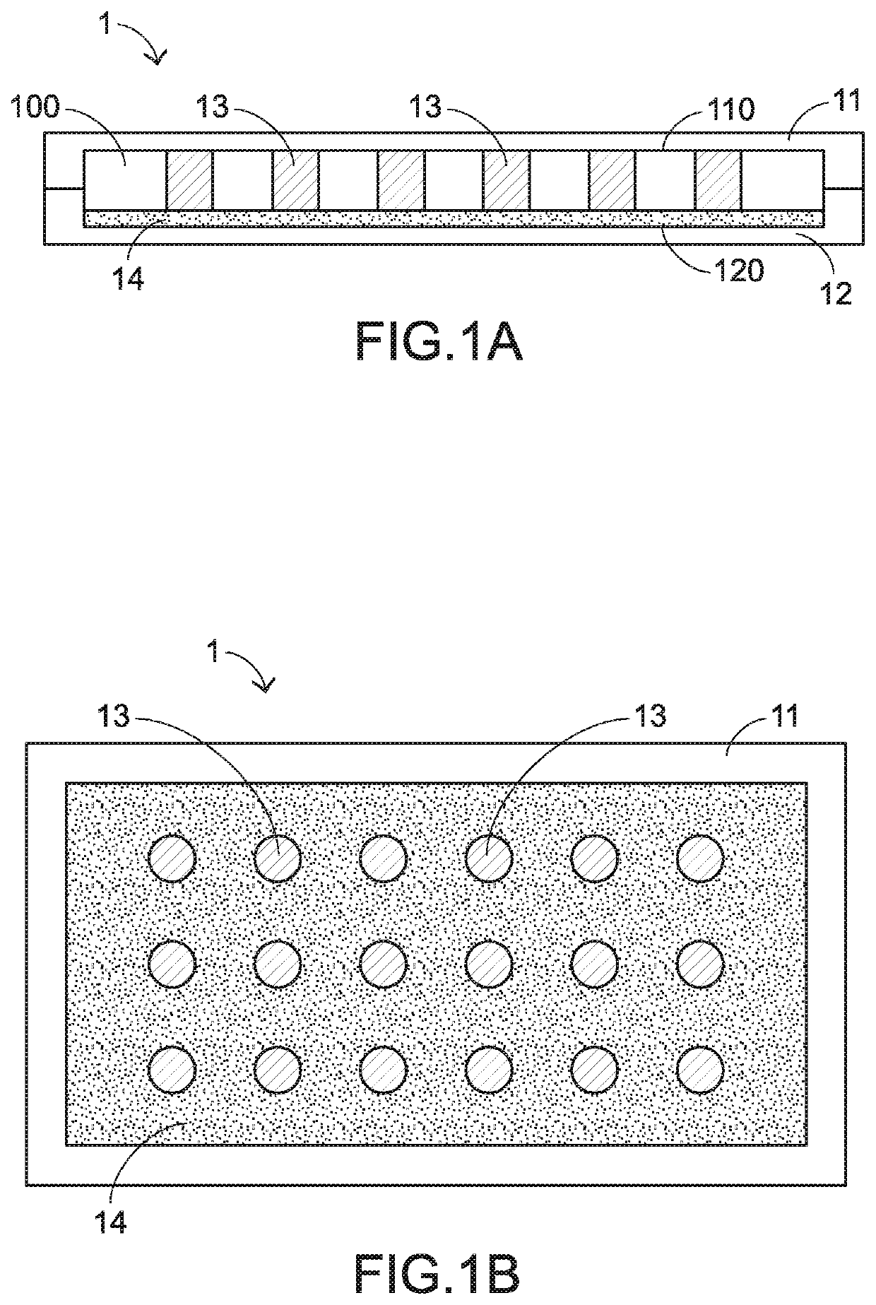
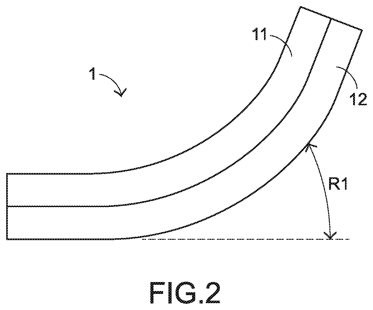
[0049]FIG. 2 schematically illustrates the application of the vapor chamber according to the present invention. In response to the flexural action of the vapor chamber 1, the vapor chamber 1 is subjected to deformation. In accordance with a design, the associated components have the flexible properties, and the plural support structures 13 and the capillary structure 14 are not suffered from excess dislocation. Consequently, the flexural action of the overall vapor chamber 1 is limited to a flexible range R1. In FIG. 2, the flexible range R1 is along the two-dimensional plane. It is noted that the flexural action of the vapor chamber 1 may be applied along any direction in the space.

[0050]The vapor chamber 1 may be applied to an electronic device (not shown). For example, the electronic device is a notebook computer, a flexible mobile phone or a flip-type mobile phone. After the vapor chamber 1 is subjected to the flexural action to comply with the electronic device, the vapor chamb...

fourth embodiment

[0065]In the above embodiments, the capillary structure is disposed on the lower cover. Alternatively, the vapor chamber further comprises an additional capillary structure. The additional capillary structure is disposed on the upper cover, arranged between the plural support structures and accommodated within the accommodation space. Since the support structures are disposed on the inner surface of the upper cover, the support structures are penetrated through the additional capillary structure. Alternatively, the additional capillary structure comprises plural copper strips, which are produced by the method as described in the Consequently, the plural copper strips are placed on the first inner surface of the upper cover successively and centralized to avoid the difficulty of disposing the entire of the copper mesh.

[0066]Alternatively, the capillary structure with the capillary function and the supporting function can be produced by a 3D printing technology or any other appropria...


PUM


Abstract

A flexible vapor chamber for an electronic device includes an upper cover, a lower cover, an accommodation space, a capillary structure, plural support structures and a working fluid. The upper cover is made of a first flexible material. The lower cover is made of a second flexible material. The accommodation space is arranged between the upper cover and the lower cover. The capillary structure is disposed on the lower cover and accommodated within the accommodation space. The plural support structures are disposed on the upper cover and accommodated within the accommodation space. The plural support structures are contacted with the capillary structure. The working fluid is accommodated within the accommodation space. The flexible vapor chamber is permitted to be subjected to a flexural action in a flexible range. Consequently, the installation of the flexible vapor chamber complies with a shape of the electronic device.

Description

FIELD OF THE INVENTION[0001]The present invention relates to a heat dissipation device, and more particularly to a vapor chamber.BACKGROUND OF THE INVENTION[0002]With the increasing development of mobile computing technologies, people have generally used various mobile electronic devices such as notebook computers or smart phones. As the mobile electronic devices are developed toward slimness, the internal spaces of the mobile electronic devices become narrower and narrower. Moreover, as the functions and performance of these mobile electronic devices are gradually enhanced, the electronic components within the mobile electronic devices generate a great deal of heat. If the heat cannot be effectively dissipated away from the narrow internal space, the elevated temperature may result in damage of the electronic components. Consequently, it is an important issue to design the heat dissipation mechanism of the mobile electronic device. The heat sink is contacted and attached to the hea...

Claims


Application Information

Patent Timeline
Patent Type & Authority Applications(United States)
IPC IPC(8): F28D15/04F28D15/02
CPCF28D15/046F28D15/0233F28D15/0241H05K7/20336H01L23/427F28F2240/00F28F2225/00
Inventor CHEN, CHIH-WEIKUO, CHE-WEICHANG, TIEN-YAOCHUANG, HSIANG-CHIH
Owner AURAS TECH
Why Eureka
Try Eureka