Drift Eliminator with Formed Beveled Tip

a technology of beveled tip and eliminator, which is applied in the direction of machine/engine, trickle cooler, combustion-air/fuel-air treatment, etc., can solve the problems of failure of the eliminator, and achieve the effect of not increasing the power requirement of moving air through the eliminator, low cost of manufacture, and durable construction

Active Publication Date: 2009-12-31
BRENTWOOD INDS
View PDF70 Cites 12 Cited by
  • Summary
  • Abstract
  • Description
  • Claims
  • Application Information

AI Technical Summary

Benefits of technology

[0014]It is another advantage of this invention that the beveled side walls prevent water droplets from forming a film over the air inlet of the corresponding tube-like passageway.
[0020]It is yet another advantage of this invention that the structural strength of the drift eliminator assembly is maintained within acceptable parameters even though the back walls of the corrugated spacer members are not in the same horizontal plane as the lower edges of the front walls of the corrugated spacer members in the drift eliminator stack.
[0023]It is a further advantage of this invention that the formation of a beveled side wall structure on the corrugated spacer member does not require a separate manufacturing step after the corrugated spacer member has been vacuumed formed and separated from the other components formed at the same time as the corrugated spacer member.
[0024]It is a further object of this invention to provide a drift eliminator assembly formed from alternating curved blade members and corrugated spacer members in which the lower edges of front and back walls of the corrugated member do not define a horizontal plane which is durable in construction, inexpensive of manufacture, carefree of maintenance, facile in assemblage, and simple and effective in use.
[0025]It is still a further object of this invention to provide a method of forming a corrugated spacer member for use in conjunction with curved blade members defining cellular tube-like passageways for the removal of water from the air passing through a drift eliminator assembly, which method is durable in construction, inexpensive of manufacture, carefree of maintenance, facile in assemblage, and simple and effective in use.

Problems solved by technology

If the air velocity exceeds the rate for which the drift eliminator is designed to operate, the drift rate increases causing the drift eliminator to fail by exceeding the specified drift rate, i.e. allowing excessive drift to be discharged from the evaporative cooling device.

Method used


Image

  • Drift Eliminator with Formed Beveled Tip
  • Drift Eliminator with Formed Beveled Tip
  • Drift Eliminator with Formed Beveled Tip

Examples


Embodiment Construction

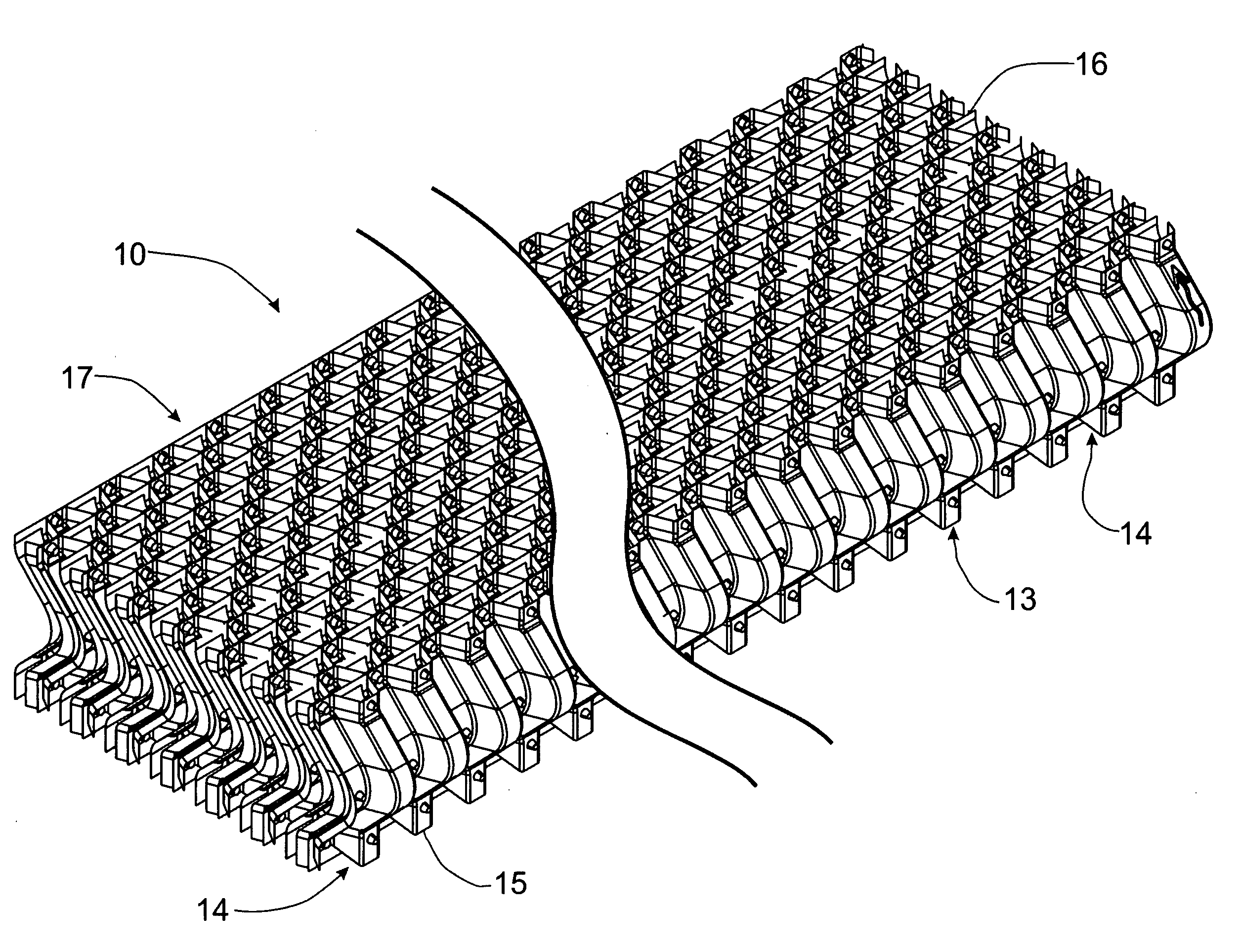
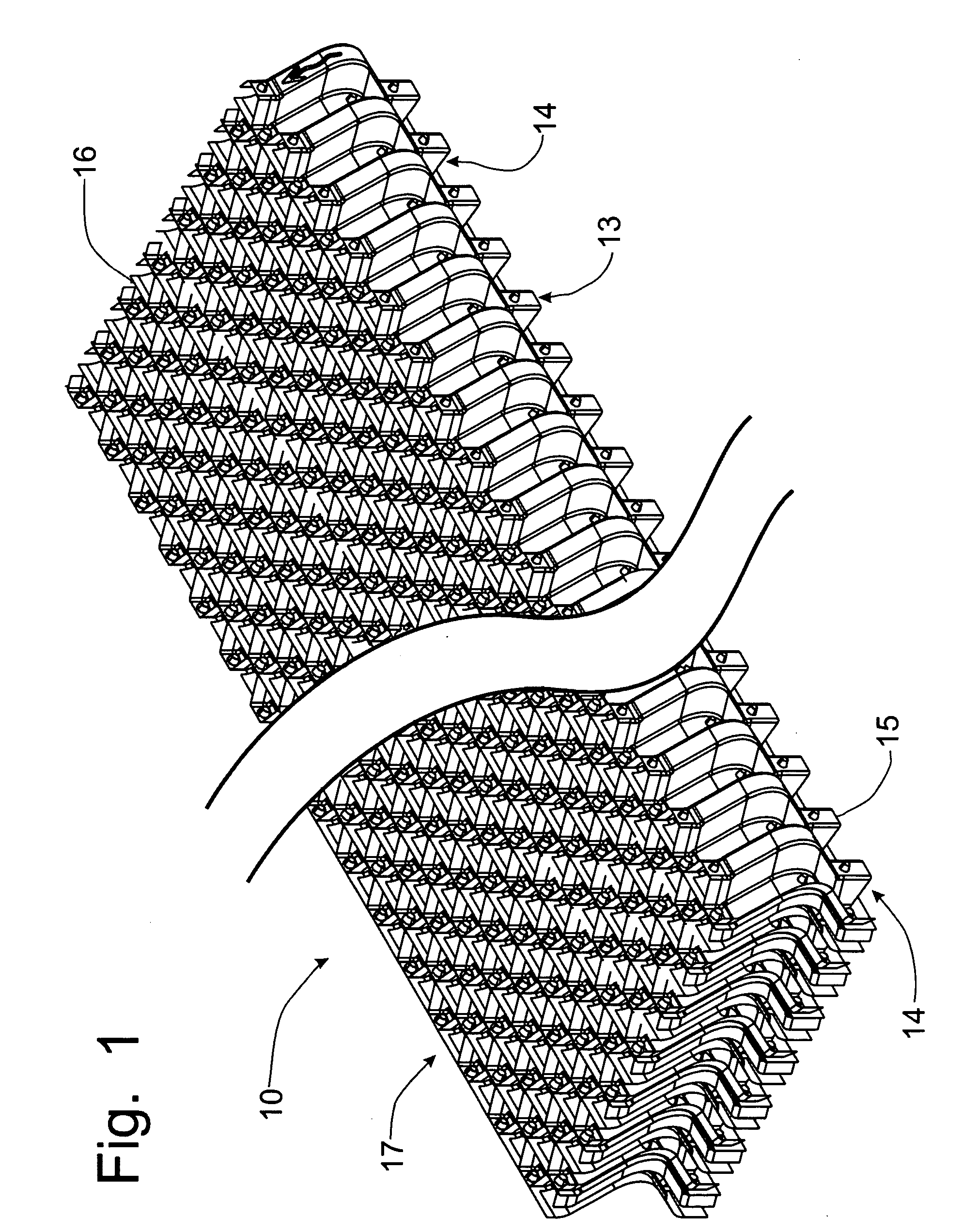
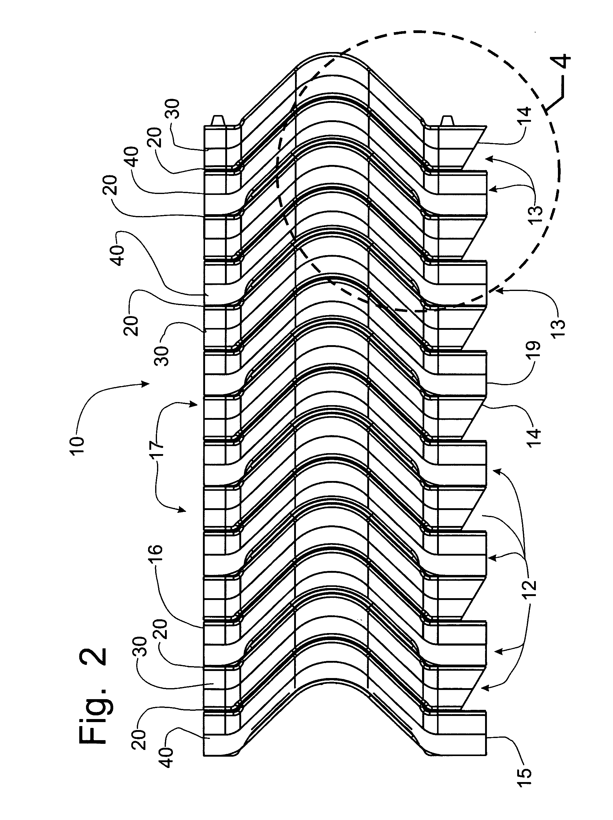
[0055]Referring first to FIGS. 1-5A, a drift eliminator assembly incorporating the principles of the instant invention can best be seen. The drift eliminator assembly 10 is formed of alternating blade members 20 and corrugated spacer members 30, 40 to define an array of cellular tube-like passageways 12 that pass through the assembly 10 from a lower surface 15 to an upper surface 16. As will be described in greater detail below, each of the cellular passageways 12 follows a curved route in traveling from the inlet openings 13 at the lower surface 15 to the discharge openings 17 at the upper surface 16. By forcing the flow of air through the drift eliminator assembly 10, water droplets entrained in the air will impinge on the curved walls of the passageways 12 and flow by gravity to the inlet openings 13 where the collected water droplets will return to the evaporative cooling apparatus (not shown) for recirculation.

[0056]As is depicted in FIGS. 4, 5 and 5A, the inlet openings 13 are...


PUM

PropertyMeasurementUnit
thicknessaaaaaaaaaa
lengthaaaaaaaaaa
angleaaaaaaaaaa

Abstract

A drift eliminator is formed from alternating curved spacers and corrugated spacer members to define tube-like passageways for the flow of air through an evaporative cooling apparatus. The formation of the corrugated blade member with beveled side walls places the back walls of the channels in a different plane than the front walls, with the lower edge of the front walls of the channels being positioned in a common plane along with the lower edge of the blade members. The angled side walls impede the formation of a film of water across the inlet opening into the channel, which requires an increase in horsepower for the fan to push air through the drift eliminator. Mechanical fastening devices molded into the respective members connects the corrugated spacer members and the blade members. A method of forming the corrugated spacer members to provide the angled side walls is also provided.

Description

FIELD OF THE INVENTION[0001]The present invention generally relates to a drift eliminator used in counter-flow cooling towers and other evaporative cooling devices to remove moisture from the flow of air through the drift eliminator and, more particularly, to a configuration of a drift eliminator that has a formed bevel tip to enhance drainage of accumulated water from blocking the air flow channels through the drift eliminator.BACKGROUND OF THE INVENTION[0002]A drift eliminator has the function of removing water droplets, entrained typically as a mist which is referred to as “drift”, from the flow of air moving through the drift eliminator. The drift eliminator is utilized in evaporative cooling devices, such as cooling towers, to reduce the water volume within the air flow being discharged from the cooling device so that the circulating water is not lost from the evaporative cooling device. By retaining the circulating water within the evaporative cooling equipment, the drift elim...

Claims


Application Information

Patent Timeline
Patent Type & Authority Applications(United States)
IPC IPC(8): B01J19/32
CPCF28C1/16B01D1/305Y02B30/70Y10S261/11Y10S454/905
Inventor KRELL, TIMOTHY E.TRUEX, ANDREW L.
Owner BRENTWOOD INDS
Why Eureka
Try Eureka