Rotary bird feeder device

Active Publication Date: 2020-10-22
LIANG HUI
View PDF0 Cites 0 Cited by
  • Summary
  • Abstract
  • Description
  • Claims
  • Application Information

AI Technical Summary

Benefits of technology

[0008]Through the combination of the direction indicator and the bird feeder, not only the direction indicator indicates the direction for others, but also birds feed on the bird feeder above the direction indicator, which has strong ornamental, smart and reasonable structure design, and strong practicality. T

Problems solved by technology

Some bird feeders have more functions, but their structures are compl

Method used


Image

  • Rotary bird feeder device
  • Rotary bird feeder device
  • Rotary bird feeder device

Examples


first embodiment

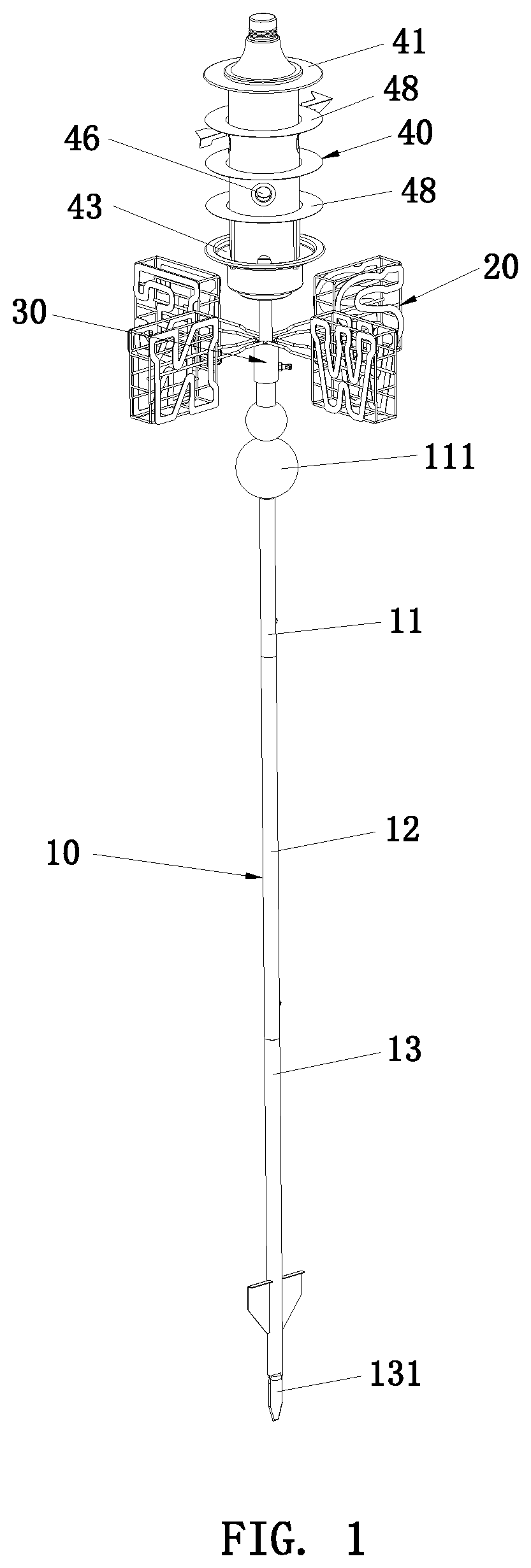
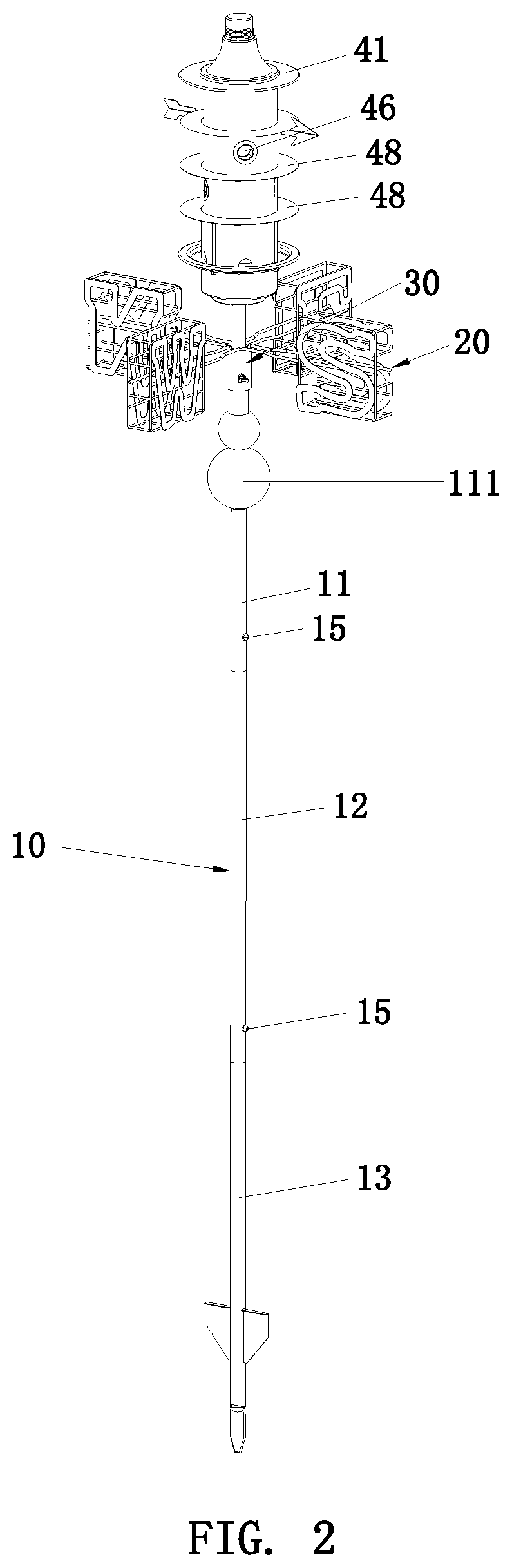
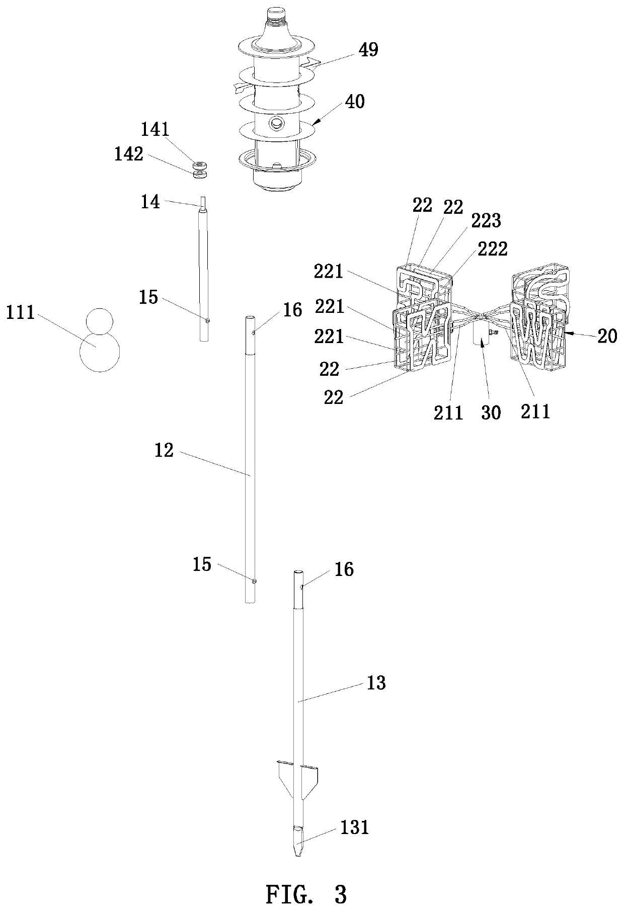
[0031]As shown in FIG. 3 and FIG. 4, in the first embodiment, the middle pole 12, the upper pole 11 and the lower pole 13 are detachably connected to each other through buckle holes 16 and buckle members 15. The middle pole 12 is provided with buckle members 15. The upper pole 11 and the lower pole 13 are provided with buckle holes 16. The buckle members 15 of the middle pole 12 are engaged in the buckle holes 16 of the upper pole 11 and the lower pole 13, so that the upper pole 11 and the lower pole 13 are connected to the middle pole 12.

[0032]Preferably, the upper end of the middle pole 12 is provided with a buckle hole 16, and the lower end of the middle pole 12 is provided with a buckle member 15. The upper pole 11 is provided with a buckle member 15. The lower pole 13 is provided with a buckle hole 16. The buckle hole 16 and the buckle member 15 of the middle pole 12 are engaged with the buckle member 15 of the upper pole 11 and the buckle hole 16 of the lower pole 13 respectiv...

second embodiment

[0033]As shown in FIG. 8 and FIG. 9, in the second embodiment, the middle pole 12, the upper pole 11 and the lower pole 13 are detachably connected to each other through internal threads and external threads. Preferably, the upper end of the middle pole 12 is provided with a first mounting hole 19, and the lower end of the middle pole 12 is provided with external threads 17. The upper pole 11 is provided with external threads 17. The lower pole 13 is provided with a second mounting hole 18. Internal threads are provided in the first mounting hole 19 and the second mounting hole 18. The first mounting hole 19 of the middle pole 12 is mated with the external threads 17 of the upper pole 11, and the external threads 17 of the middle pole 12 is mated with the second mounting hole 18 of the lower pole 13 to form an assembled connection of the middle pole 12, the upper pole 11 and the lower pole 13.

[0034]Of course, the connection of the upper pole 11, the middle pole 12 and the lower pole...


PUM


Abstract

A rotary bird feeder device includes a direction indicator and a bird feeder. Through the combination of the direction indicator and the bird feeder, not only the direction indicator indicates the direction for others, but also birds feed on the bird feeder above the direction indicator, which has strong ornamental, smart and reasonable structure design, and strong practicality. The bird feeder has a rotating function to facilitate cleaning of the outside of the bird feeder. By providing a bird feeding space for storing birdseed in the direction indicator, the direction indicator has the function of a bird feeder, and the space design of the direction indicator is skillfully utilized.

Description

BACKGROUND OF THE INVENTION1. Field of the Invention[0001]The present invention relates to a bird feeder device, and more particularly to a rotary bird feeder integrated with a direction indicator.2. Description of the Prior Art[0002]Conventional bird feeders are usually hung in branches, eaves or other higher positions where the bird feeders can be suspended. Some bird feeders are installed through a pole. In the prior art, some bird feeders have a simple structure, but their corresponding functions are few. Some bird feeders have more functions, but their structures are complicated so the cost for the structural design and installation is high.[0003]Accordingly, the inventor of the present invention has devoted himself based on his many years of practical experiences to solve these problems.SUMMARY OF THE INVENTION[0004]In view of the drawbacks of the prior art, the primary object of the present invention is to provide a rotary bird feeder device. Through the combination of a dire...

Claims


Application Information

Patent Timeline
IPC IPC(8): A01K39/01
CPCA01K39/01
Inventor LIANG, HUI
Owner LIANG HUI
Why Eureka
Try Eureka