Artificial knee joint

a knee joint and artificial technology, applied in the field of artificial knee joints, can solve the problems of not meeting the above requirements, lack of cruciate ligaments and menisci in the knee joint after surgery, and the inability to achieve the desired recovery effect after such an operation

Active Publication Date: 2020-12-10
ZHU HONGWEN
View PDF0 Cites 0 Cited by
  • Summary
  • Abstract
  • Description
  • Claims
  • Application Information

AI Technical Summary

Problems solved by technology

However, the current mainstream surgical methods and artificial knee joints are far from meeting the above requirements.
However, in the current popular knee replacement surgery, the natural tibial plateau is often directly removed, replaced with an artificial tibial plateau, and a similarly shaped femoral condyle prosthesis is installed on the femoral surface, so that the new femoral condyle prosthesis interact with the artificial tibial plateau, which lead to the absence of cruciate ligaments and menisci in the knee joint after surgery, and some even the patella.
Therefore, the current surgical method and the characteristics of the corresponding artificial knee joint make it impossible to have the desired recovery effect after such an operation.
Such surgery destroys the original physiological structure and characteristics of the knee joint, and causes permanent irreversible damage to the knee joint.
The medial condyle or plateau is damaged first, and then the other condyle or plateau is accelerated and the patient suffers great pain during this process.
Although this idea is worth promoting, it encountered great difficulties in the actual implementation process, which ultimately could not be achieved, or its real effect was lower than the original monolithic knee joint; the main problem is that when the semi-condylar knee joint is replaced, the replacement part does not match the function and height of the intact part, which cannot effectively delay the damage rate of the intact part.
After the other intact part of the knee joint is also damaged, the artificial knee joint still needs to be replaced by surgery.
At this time, if the semi-condylar knee joint is also used, the two semi-condylar knee joints are difficult to coordinate in terms of height, size and elasticity, and the use effect is poor.
If the monolithic knee joint is used to replace, the originally replaced semi-condylar knee joint becomes meaningless, and it also involves the secondary damage installation of the tibia and femur.

Method used


Image

  • Artificial knee joint
  • Artificial knee joint
  • Artificial knee joint

Examples


Embodiment Construction

Hereinafter, the present invention will be explained in more detail with reference to figures and examples. Through these explanations, the features and advantages of the present invention will become clearer.

[0083]The term “exemplary” as used herein is intended to be “serving as an example, an embodiment, or an illustrative embodiment”. Any of the embodiments described herein as “exemplary” need not be construed as preferred as or better than other embodiments. Although various aspects of the embodiments are shown in the figures, it is not necessary to draw a figure in proportion unless otherwise specified.

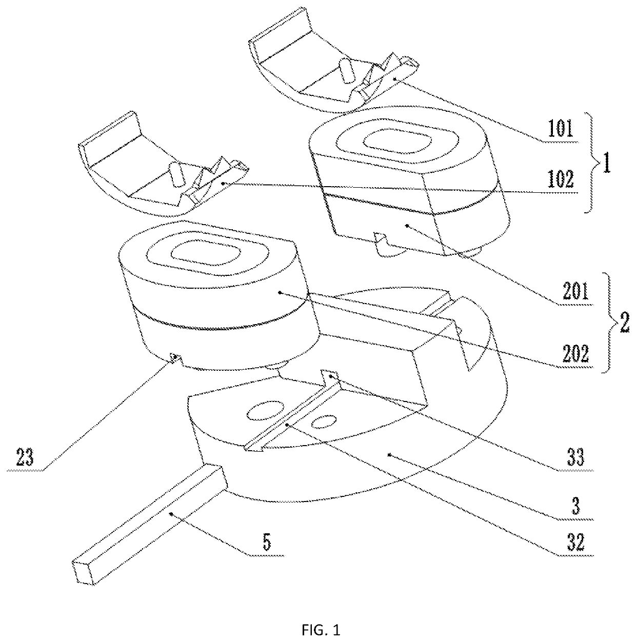
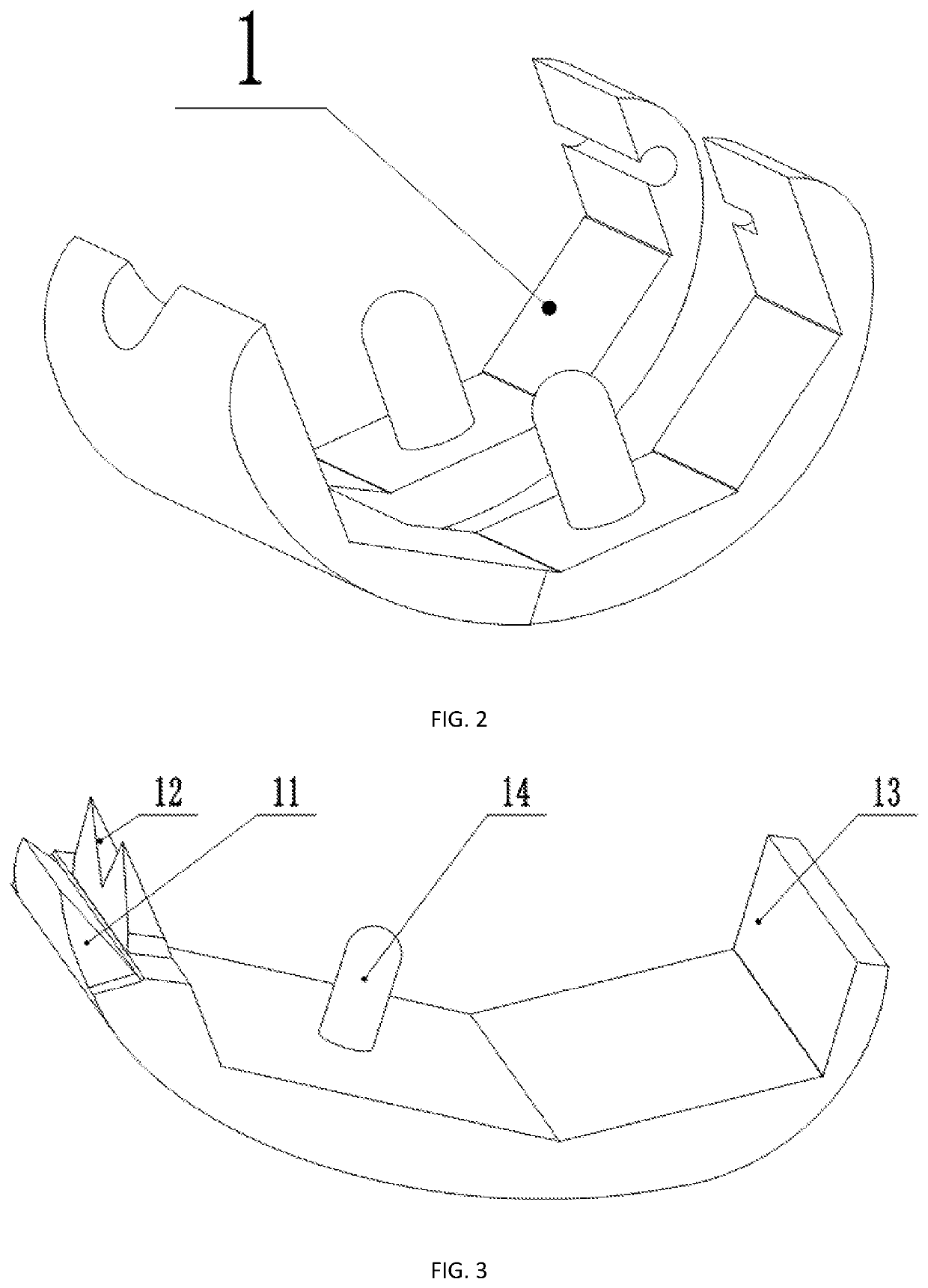
[0084]The artificial knee joint provided according to the present invention is shown in FIG. 1. The artificial knee joint includes a femoral condyle prosthesis 1 and a tibial plateau prosthesis 2, wherein, the femoral condyle prosthesis 1 is disposed at the lower end of the femur 8 and replaces a part of the bone structure at the lower end of the femur, and the tibial plateau pro...


PUM


Abstract

The invention describes an artificial knee joint, which includes a femoral condyle prosthesis and a tibial plateau prosthesis, and said tibial plateau prosthesis includes a medial tibial plateau prosthesis and a lateral tibial plateau prosthesis respectively disposed at both sides of the tibial plateau intercondylar eminence. The artificial knee joint further includes a locating pin for fixing the tibial plateau prosthesis. The bottom surface of said tibial plateau prosthesis is provided with a prosthetic notch, and the tibia below said tibial plateau prosthesis is provided with a tibial notch. Said prosthetic notch corresponds to said tibial notch, together forming a limiting hole for accommodating the locating pin. The cooperation between the locating pin and the limiting hole can ensure relative position stability and balance between the medial tibial plateau prosthesis and the lateral tibial plateau prosthesis.

Description

TECHNICAL FIELD[0001]The invention relates to a medical artificial joint prosthesis, particularly relates to an artificial knee joint.BACKGROUND ART[0002]At present, knee replacement surgery is the world's most fundamental treatment for knee diseases and injuries. In replacement surgery, joint prostheses, also called artificial knee joints, are implanted into the human body to replace the body's natural knee joints. With the gradual advancement of science and technology, further requirements for artificial knee joints and replacement surgery are becoming higher and higher. People hope not only to reduce pain, but also to increase their service life. They also hope to achieve better postoperative recovery, and even hope to reach the level of normal healthy people. For these reasons, various artificial knee joints have gradually come out, and various ideas have been proposed. However, the current mainstream surgical methods and artificial knee joints are far from meeting the above req...

Claims


Application Information

Patent Timeline
Patent Type & Authority Applications(United States)
IPC IPC(8): A61F2/38
CPCA61F2002/30133A61F2/389A61F2002/30546A61F2002/30565A61F2/3836A61F2002/4631A61F2/3859A61F2002/30428A61F2002/30354A61F2/3872A61F2/3854A61F2/3877A61F2002/3006A61F2002/30476A61F2002/3065A61F2002/30649A61F2002/30654A61F2/38A61F2002/30143A61F2002/30153A61F2002/30154A61F2002/30158A61F2002/30329A61F2002/30398A61F2002/30492A61F2002/30507A61F2002/30566A61F2002/30576A61F2002/30604A61F2002/30772A61F2002/30784A61F2002/30841A61F2002/30878A61F2002/30891A61F2002/30934A61F2002/3881A61F2002/3895A61F2220/0025A61F2250/0012
Inventor ZHU, HONGWENHUANG, GUOFUDONG, RONGHUAZHU, TIANMOU
Owner ZHU HONGWEN
Why Eureka
Try Eureka