Hydrolic accommodating intraocular lens

a technology of intraocular lens and hydrophilic material, which is applied in the field of hydrophilic accommodating intraocular lens, can solve the problems of acrylic material fracture if repeated flexing, limited materials from which the lens can be folded, and the lens could not fixate well in the capsular bag, etc., so as to reduce the radius of the anterior surface, increase the curvature, and simulate the effect of function

Inactive Publication Date: 2011-07-19
C& C VISION INT
View PDF82 Cites 48 Cited by
  • Summary
  • Abstract
  • Description
  • Claims
  • Application Information

AI Technical Summary

Benefits of technology

[0009]The lens of the present invention is made of solid silicon with liquid silicone both of which have the same refractive index, and have a specific gravity the same as or very similar to that of the aqueous solution of the natural eye. The power of the lens, before implantation into the eye, can be changed by (1) changing the radius of a posterior portion of the optic, and / or (2) by changing the volume of the liquid silicone in the lens optic during the manufacturing process, or after implantation by injecting liquid silicone of the same or different refractive index into the cavity of the lens. During accommodation with contraction of the ciliary muscle and an increase in the vitreous cavity pressure the posterior surface of the solid silicone posterior portion of the lens is pushed forward since it is surrounded by a silicone membrane. This causes bulging of a thinner anterior membrane thereby increasing its curvature, thus decreasing the radius of the anterior surface of the lens, for near vision. The thin anterior membrane may be thicker in its periphery such that an increase in pressure inside the lens would product a central bulging of the membrane. This structure simulates the structure of the anterior capsule of the human lens and simulates its function. The posterior solid central. optic portion may have additional single or multiple spherical components or may be aspherical on one or both of its surfaces. Also, the increase in vitreous cavity pressure can tilt the lens to further facilitate accommodation.
[0010]Accordingly, features of the present invention are to provide an improved form of accommodating lens formed from solid and liquid silicone.

Problems solved by technology

These lenses could be folded but did not fixate well in the capsular bag, but resided in pockets between the anterior and posterior capsules.
The advent of an accommodating lens which functions by moving along the axis of the eye by repeated flexions somewhat limited the materials from which the lens could be made.
On the other hand, acrylic material fractures if it is repeatedly flexed.

Method used


Image

  • Hydrolic accommodating intraocular lens
  • Hydrolic accommodating intraocular lens
  • Hydrolic accommodating intraocular lens

Examples


Embodiment Construction

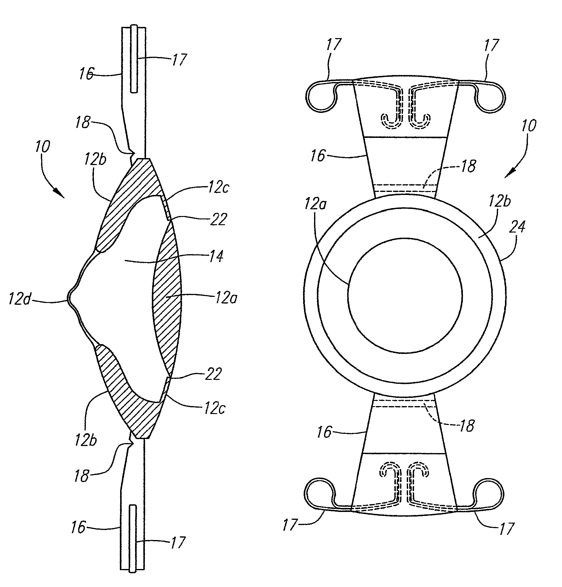
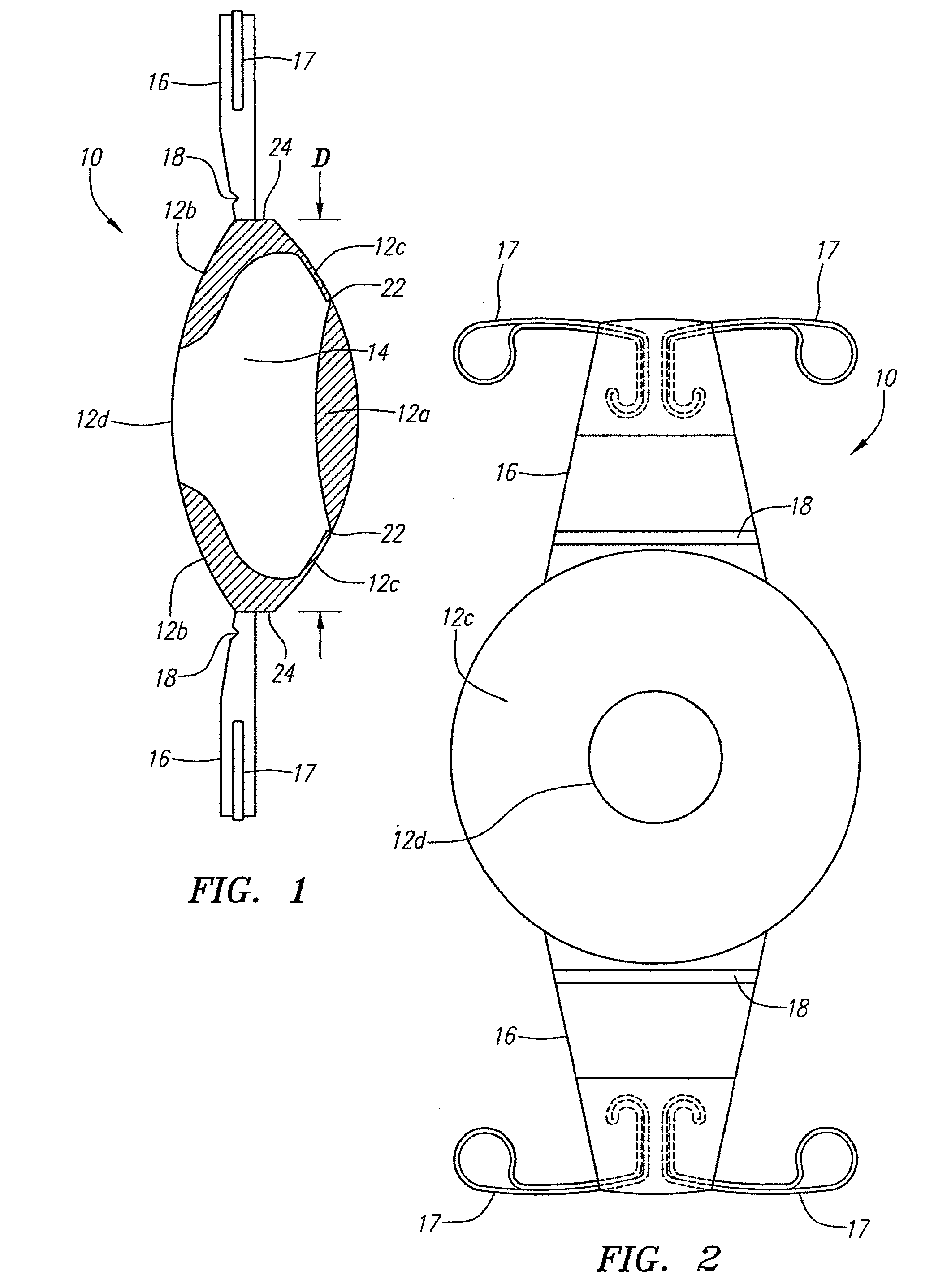
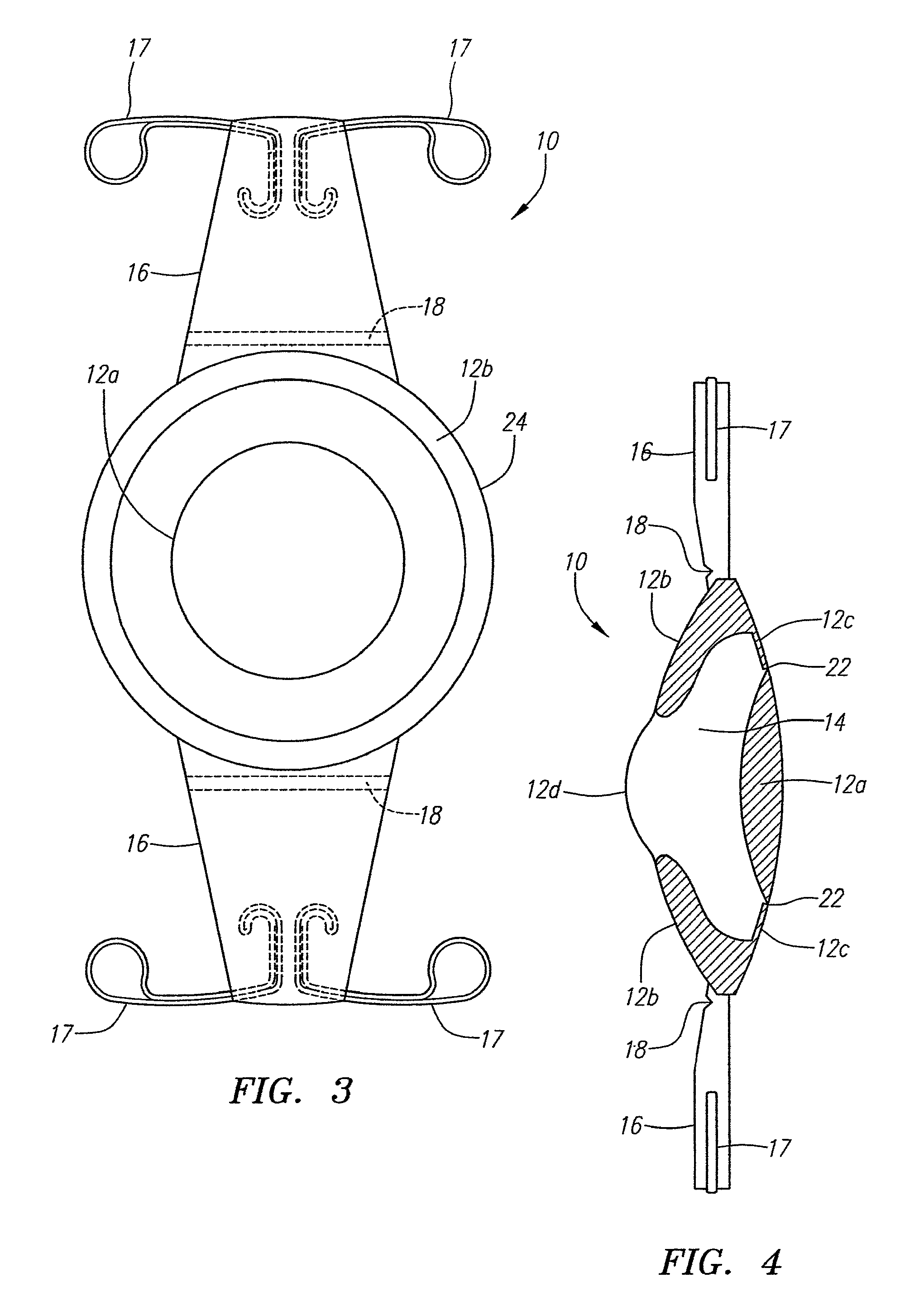
[0017]Turning now to the drawings, a preferred embodiment is shown in detail, comprising an intraocular lens with an optic 10 and haptics 16. The optic 10 is formed of two components, namely, a flexible solid portion 12 (12a-12d) preferably made of silicone, acrylic or hyrdrogel, and an interior liquid silicone portion 14. The portions 12a and 12b are sufficiently solid to prevent defomation of the optic 10 upon implantation into the fibrosed capsular bag of the eye. The flexible extending portions 16 may be plate haptics which are capable of multiple flexations without damage, and formed, for example, of silicone. The optic 10 and haptics 16 preferably are uniplanar, and two or more haptics 16 extend distally from opposite sides of the optic 10. The outer ends of the haptics 16 may include flexible fingers 17 such as disclosed in U.S. Pat. No. 6,387,126 to Cumming. Preferably the edge 24 of the optic is a 360° square edge.

[0018]The lens 10 includes portions 12a, 12b and 12d of soli...


PUM


Abstract

An accommodating intraocular lens comprising an optic made from solid silicone and liquid silicone. The optic has a central anterior area or membrane that can vary in radius and thus change power.

Description

[0001]This application is a continuation-in-part of application Ser. No. 11 / 297,232 filed Dec. 7, 2005, now abandoned, the disclosure of which is expressly incorporated herein by reference.BACKGROUND[0002]Intraocular lenses have for many years had a design of a single optic with loops attached to the optic to center the lens and fixate it in the empty capsular bag of the human lens. In the mid '80s plate lenses were introduced, which comprised a silicone lens, 10.5 mm in length, with a 6 mm optic. These lenses could be folded but did not fixate well in the capsular bag, but resided in pockets between the anterior and posterior capsules. The first foldable lenses were all made of silicone. In the mid 1990s an acrylic material was introduced as the optic of lenses. The acrylic lens comprised a biconvex optic with a straight edge into which were inserted loops to center the lens in the eye and fixate it within the capsular bag.[0003]Recently accommodating intraocular lenses have been i...

Claims


Application Information

Patent Timeline
Patent Type & Authority Patents(United States)
IPC IPC(8): A61F2/16
CPCA61F2/1613A61F2/1635A61F2250/0018A61F2/16A61F2/14A61L27/14
Inventor CUMMING, J. STUART
Owner C& C VISION INT
Why Eureka
Try Eureka