Acoustic wave device

a technology of acoustic waves and filters, applied in the direction of impedence networks, electrical devices, etc., can solve the problem of unsatisfactory deterioration of filter characteristics

Active Publication Date: 2020-12-10
MURATA MFG CO LTD
View PDF0 Cites 1 Cited by
  • Summary
  • Abstract
  • Description
  • Claims
  • Application Information

AI Technical Summary

Benefits of technology

The present invention provides acoustic wave devices that can prevent the occurrence of a spurious mode outside a pass band. This means that these devices can effectively filter out unwanted signals that may affect the quality of a signal transmission.

Problems solved by technology

However, use of the acoustic wave device described in International Publication No. 2012 / 086639 as a filter may undesirably deteriorate filter characteristics due to an occurrence of spurious modes outside a pass band of the filter.

Method used


Image

  • Acoustic wave device
  • Acoustic wave device

Examples


Embodiment Construction

[0012]Preferred embodiments of the present invention are described below with reference to the drawings.

[0013]The preferred embodiments below are illustrative, and an element in one preferred embodiment may be replaced or combined with an element in another preferred embodiment.

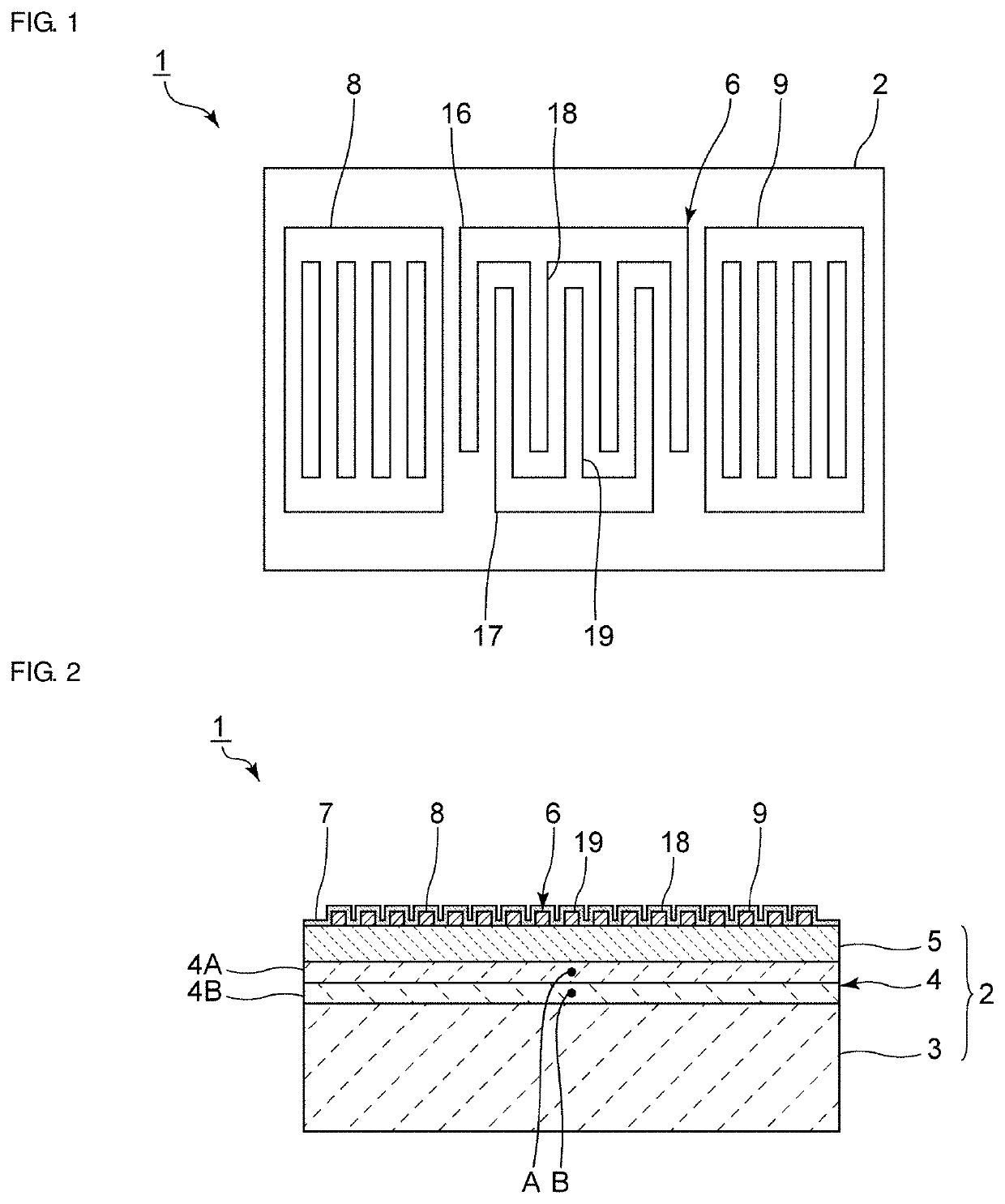
[0014]FIG. 1 is a plan view of an acoustic wave device according to a first preferred embodiment of the present invention. In FIG. 1, a dielectric film, which will be described later, is omitted.

[0015]An acoustic wave device 1 includes a piezoelectric substrate 2. An IDT electrode 6 is provided on the piezoelectric substrate 2. An acoustic wave is excited by application of an alternating-current voltage to the IDT electrode 6. On the piezoelectric substrate 2, the IDT electrode 6 is sandwiched between a pair of reflectors 8 and 9 in a direction in which the acoustic wave propagates. That is, the acoustic wave device 1 according to the present preferred embodiment is an acoustic wave resonator. Note, however, ...


PUM


Abstract

An acoustic wave device includes a high-acoustic-velocity support substrate, a low-acoustic-velocity film provided on the high-acoustic-velocity support substrate, a piezoelectric layer provided on the low-acoustic-velocity film, and an IDT electrode provided on the piezoelectric layer. An acoustic velocity of a bulk wave propagating through the high-acoustic-velocity support substrate is higher than an acoustic velocity of an acoustic wave propagating through the piezoelectric layer. An acoustic velocity of a bulk wave propagating through the low-acoustic-velocity film is lower than an acoustic velocity of a bulk wave propagating through the piezoelectric layer. The low-acoustic-velocity film has a first portion and a second portion that is located closer to the high-acoustic-velocity support substrate than the first portion. The first and second portions include the same or similar materials. A density in the first portion of the low-acoustic-velocity film and a density in the second portion of that are different.

Description

CROSS REFERENCE TO RELATED APPLICATIONS[0001]This application claims the benefit of priority to Japanese Patent Application No. 2019-106106 filed on Jun. 6, 2019. The entire contents of this application are hereby incorporated herein by reference.BACKGROUND OF THE INVENTION1. Field of the Invention[0002]The present invention relates to an acoustic wave device.2. Description of the Related Art[0003]An acoustic wave device has been widely used, for example, as a filter for a mobile phone. International Publication No. 2012 / 086639 discloses an example of an acoustic wave device. This acoustic wave device has a multilayer body in which a high-acoustic-velocity support substrate, a low-acoustic-velocity film, and a piezoelectric film are laminated in this order and an interdigital transducer (IDT) electrode provided on the piezoelectric film. Due to the multilayer body, a Q factor increases.[0004]However, use of the acoustic wave device described in International Publication No. 2012 / 086...

Claims


Application Information

Patent Timeline
Patent Type & Authority Applications(United States)
IPC IPC(8): H03H9/02H03H9/17
CPCH03H9/02086H03H9/17H03H9/02015H03H9/02228H03H9/174H03H9/547H03H9/02574H03H9/02929H03H9/02866
Inventor IWAMOTO, HIDEKI
Owner MURATA MFG CO LTD
Why Eureka
Try Eureka