Windshield wiper system and vehicle comprising this system
Active Publication Date: 2020-12-24
VOLVO LASTVAGNAR AB
View PDF0 Cites 0 Cited by
Summary
Abstract
Description
Claims
Application Information
AI Technical Summary
This helps you quickly interpret patents by identifying the three key elements:
Problems solved by technology
Method used
Benefits of technology
Benefits of technology
The invention allows the windshield wiper to move along the windshield in addition to pivoting, which makes it easier to clean a larger surface of the windshield. This applies to windshields of large dimensions and curved shapes as well. The guiding rail does not need to extend along the entire length of the windscreen, which saves space and makes it easier to integrate the system inside the vehicle. Overall, the invention improves the efficiency and flexibility of windshield cleaning.
Problems solved by technology
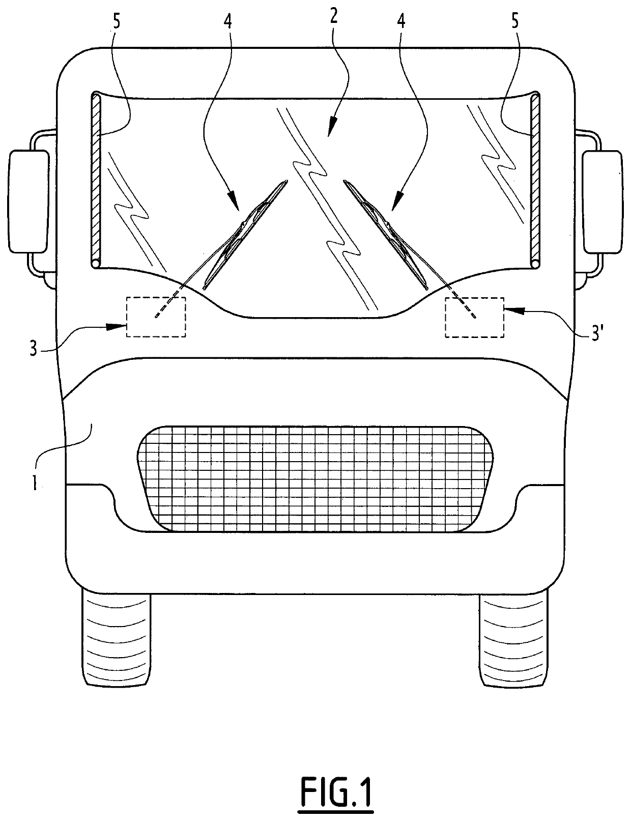
Windshields of such shapes and dimensions are difficult to clean with classical wiper blade systems, in which wiper blades are each hinged around a fixed point near the base of the windshield.
In practice, the wiped surface is limited by the length of the wipers so that many regions of the windshield remain out of reach of the wipers and cannot be cleaned.
Increasing the length of the wiper arms and blades is not always feasible, as it would require increasing the torque applied to the wipers and make them more prone to mechanical failure.
Additionally, the rotating movement of the blade is not suited to curved surfaces.
However, the system is not well suited to large windshields.
One of the reasons is that it requires the rail to extend along the entire length of the windshield, which complicates the integration of the system in the vehicle.
Method used
Image
Click on the blue label to locate the original text in one second.
Reading with bidirectional positioning of images and text.
Examples
first embodiment
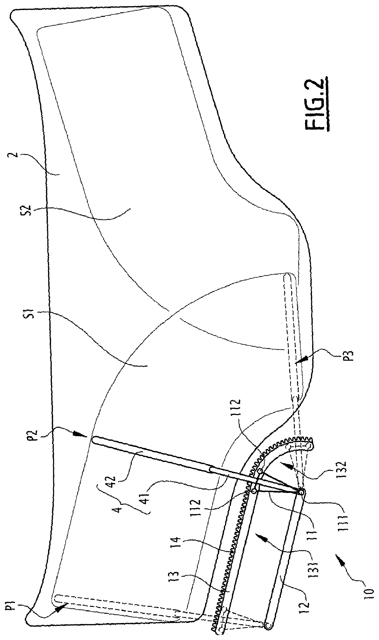
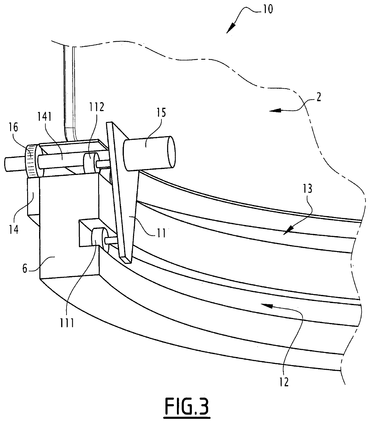
[0022]FIGS. 2 and 3 illustrate a first exemplary embodiment of the wiper system 3. In what follows, the wiper system bears the reference “10”.
[0023]The wiper system 10 includes a movable support element 11, a guiding device for guiding the support element 11 along a predefined trajectory, and a motor 15 mounted on the support element 11. In this embodiment, the predefined trajectory corresponds to the translation between positions P1 and P2 and then the rotation between positions P2 and P3.
[0024]The wiper 4 is mounted on the support element 11. For example, the arm 41 of the wiper 4 is connected to the support element 11. Preferably, the wiper 4 is fixed on the support element 11 with no degree of freedom in rotation.
[0025]In this example, the support element 11 is a rigid support plate, made of metal or plastic. The illustrated support plate has a triangle shape, although other shapes are possible.
[0026]The guiding device includes a first rail 12 and a second rail 13. In this exam...
second embodiment
[0041]FIG. 4 illustrates a second exemplary embodiment of the wiper system 3. In what follows, this second embodiment bears the reference “20”. The elements of this wiper system 20 which are similar to the wiper system 10 bear the same references and are not described in detail in what follows, given that the description above can be transposed to these elements. Thus, only the major differences between the wiper systems 20 and 10 are described below.
[0042]The wiper system 20 includes a movable support element 21, a guiding device 22 for guiding the support element 21 along a predefined trajectory, a first motor 24 mounted on the support element 11 and a second motor 23 mounted on the support element 21. In this embodiment, the predefined trajectory corresponds to the translation between positions P1 and P2.
[0043]In this example, the support element 21 is a rigid support plate, made of metal or plastic. The illustrated support plate has a rectangle shape, although other shapes are p...
PUM
Abstract
A windshield wiper system (3, 3′) for wiping a windshield (2) of a vehicle (1) includes a wiper (4) mounted on a movable support element, a guiding device for guiding the support element along a predefined trajectory and a motor mounted on the support element and arranged for providing traction power to move the support element along the predefined trajectory. The wiper system is arranged to move the wiper (4), relative to the windshield, with a translation movement between first and second positions, and with a rotation movement around a rotation axis perpendicular to the windshield between the second position and a third position.
Description
TECHNICAL FIELD OF THE INVENTION[0001]The present invention relates to a windshield wiper blade system and to a vehicle including this system.BACKGROUND OF THE INVENTION[0002]Trucks and other industrial vehicles generally have large windshields in order to offer a large field of vision to a driver of the vehicle. In some cases, the windshields can have a curved shape, for example to provide a better lateral field of vision.[0003]Windshields of such shapes and dimensions are difficult to clean with classical wiper blade systems, in which wiper blades are each hinged around a fixed point near the base of the windshield. In practice, the wiped surface is limited by the length of the wipers so that many regions of the windshield remain out of reach of the wipers and cannot be cleaned. Increasing the length of the wiper arms and blades is not always feasible, as it would require increasing the torque applied to the wipers and make them more prone to mechanical failure. Additionally, the ...
Claims
Application Information
Patent Timeline
Application Date:The date an application was filed.
Publication Date:The date a patent or application was officially published.
First Publication Date:The earliest publication date of a patent with the same application number.
Issue Date:Publication date of the patent grant document.
PCT Entry Date:The Entry date of PCT National Phase.
Estimated Expiry Date:The statutory expiry date of a patent right according to the Patent Law, and it is the longest term of protection that the patent right can achieve without the termination of the patent right due to other reasons(Term extension factor has been taken into account ).
Invalid Date:Actual expiry date is based on effective date or publication date of legal transaction data of invalid patent.

