
Apparatus and process for amateur ductless HVAC installation

a technology of ductless hvac and installation apparatus, which is applied in the field of hvac solutions, can solve the problems of high cost, complex installation process, and high cost of end-users in the modern marketplace, and achieve the effect of safe disconnection and effective cooling and/or heating

Inactive Publication Date: 2021-01-07
JOI HLDG LLC
View PDF29 Cites 1 Cited by
  • Summary
  • Abstract
  • Description
  • Claims
  • Application Information

AI Technical Summary

Benefits of technology

[0028]There is an additional need for the line-set of the system of the present invention to be outfitted with a conduit protection apparatus configured to ensure that installation by the amateur yields a safe and damage-free result. Such a protection apparatus is preferably present in the form of a spring-like coil which circumscribes the entirety of the line-set to prevent bends of the line-set during installation beyond a specific angular tolerance to prevent any compromise of the integrity of the line-set.
[0031]Accordingly, several advantages of one or more aspects of the present invention are preferably as follows: to provide an HVAC system that does not require connection to ductwork, that can be installed without special tools, which, when operational, provides a leak-free seal between the refrigerant lines and the main components. The system of the present invention can be mounted high on a wall to evenly distribute conditioned air throughout a zone. Additionally, the system can be manufactured in varying capacities to address variable air comfort needs, and that can be safely disconnected without refrigerant loss should movement be required, that will effectively provide cooling and / or heating, and that will function at an efficiency level in line with current consumer and industry expectations.

Problems solved by technology

This system has resulted in a modern marketplace with very high costs for the end-user.
Product technology and design is the main force driving these high costs.
While the exact chemical formula has changed over the years, chemical refrigerants are the best technology by which to modify interior air temperature, but their presence in the system vastly complicates the installation process.
Socioeconomic factors further stratified air conditioners and heat pumps into expensive products requiring specialist assistance to utilize.
Non-certified installation often voids the warranty agreement.
The near monopoly some local companies held on certain brands reinforced the tendency to inflate price.
The design is fundamentally sound, but has its own problems.
The requisite compact footprint of the design forced a compromise in terms of capability.
The miniaturized coils and compressor condition air, but at decreased efficiency compared to traditional ducted installations.
Higher energy costs in the intervening years have exacerbated the problem.
Air distribution is another problem with the room air conditioner.
The through-the-wall or window installation combined with a comparably simple fan limit the design's ability to move air effectively throughout an interior environment.
Unfortunately, the reliance on a standard wall outlet for power generation limited the product operating capacity.
The refrigerant line coupling point was also inferior compared to conventional connections at the time and modern techniques.
Unfortunately, this design alone is inadequate to deal with the innumerable variables found in non-manufactured housing.
These make it difficult or impossible to use a pre-charged line of specific length with a ducted split system.
The downside of the Lingrey's ductless mini-split system is its reliance on a standard wall outlet for power, and its use of a locking lever-style dual-refrigerant connector.
The locking lever-style connection can operate effectively, but it is prone to leaking and can be difficult to detach without suffering refrigerant loss after the connection is made.
(a) Overall energy efficiency has been a problem with many of the room air conditioner designs. Efficiency optimization was not a major consideration for HVAC products when Brugler (1969) and Manganaro (1971) created their designs, but the market has changed considerably in the intervening four decades. Federal law holds manufacturers to higher standards than in the past. Eco-conscious and cost-concerned consumers also expect HVAC products to meet certain thresholds.
(b) The principle advantage a simpler HVAC product offers the end-user is the ability to utilize air conditioning technology without being forced to handle and / or manipulate chemical refrigerants. Virtually all previous designs strive towards this paradigm, but many fall short in one way or another. Some create connection points prone to leakage while others are difficult to disengage once the line is connected to the condenser. The former defeats the purpose of the product in the first place while the latter may merely prolong the period before a skilled technician is required to service the operating system.
(c) The trend to rely on a standard electrical wall outlet to power the unit eliminates the need for an electrician to wire the system, but can drastically reduce the potential capacity any such system might produce. This significantly limits the application of such products. As some of the designs require cutting through a wall for installation, the versatility offered by reliance on a wall outlet as opposed to conventional wiring is compromised.
(d) Inadequate airflow and uneven distribution are perennial problems for room air conditioners. The ability to install in an existing window frame grants flexibility, but severely limits airflow movement in a target zone. The aforementioned reliance on a wall outlet electrical connection also limits the power available to operate the interior fan. Ineffective conditioned air control serves to limit the applications in which such a product can reasonably function.
Flexible conduit tubing is designed to flex, however it is usually unable to flex near or beyond 90 degrees due to the nature of the seals of the flexible housing of the conduit tubing.
Unfortunately, conduit can be over-flexed during installation, especially by a novice, or when installation is performed in a hurry.
When flexible conduit (line-set) is bent too far, irreparable damage to the conduit occurs, often causing one or more holes in the conduit tubing.
In such cases, instead of the conduit bending and having a sealed tube within it, the tube is folded, which may cause breakage, or at the least, weaken the piping.
This causes a problem of the conduit piping having a crimp in the bend, restricting the flow inside.
A hard bend or crimp such as this can also cause holes, causing it to leak.
Breakage generally occurs when an improper bending technique is used, which can cause imperceptible defects in the metal when under stress.

Method used


Image

  • Apparatus and process for amateur ductless HVAC installation
  • Apparatus and process for amateur ductless HVAC installation
  • Apparatus and process for amateur ductless HVAC installation

Examples


Embodiment Construction

[0057]The present specification discloses one or more embodiments that incorporate the features of the invention. The disclosed embodiment(s) merely exemplify the invention. The scope of the invention is not limited to the disclosed embodiment(s). The invention is defined by the claims appended hereto.

[0058]References in the specification to “one embodiment,”“an embodiment,”“an example embodiment,” etc., indicate that the embodiment described may include a particular feature, structure, or characteristic, but every embodiment may not necessarily include the particular feature, structure or characteristic. Moreover, such phrases are not necessarily referring to the same embodiment, Further, when a particular feature, structure, or characteristic is described in connection with an embodiment, it is submitted that it is within the knowledge of one skilled in the art to effect such feature, structure, or characteristic in connection with other embodiments whether or not explicitly descr...


PUM

PropertyMeasurementUnit
lengthaaaaaaaaaa
forceaaaaaaaaaa
temperatureaaaaaaaaaa

Abstract

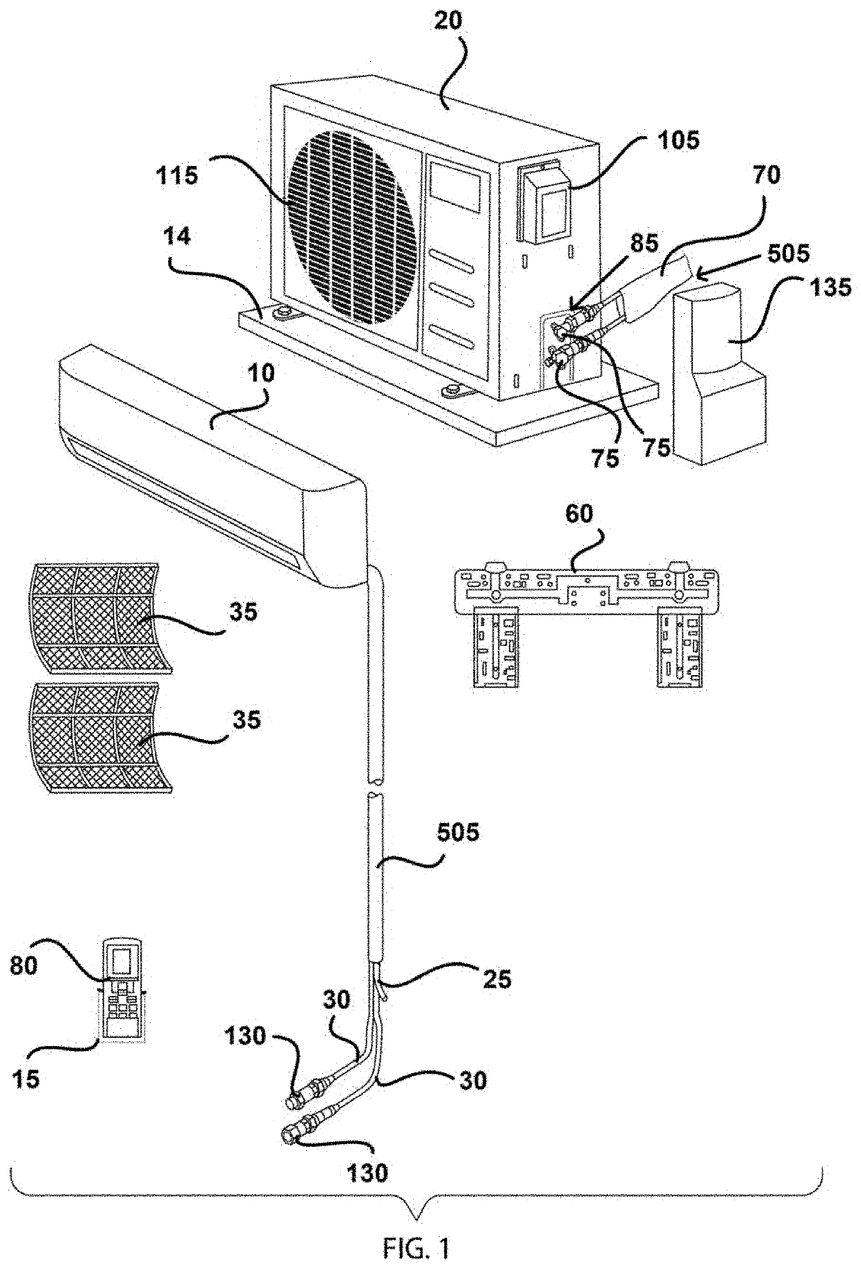
Apparatuses, systems, and methods for providing non-expert installation of HVAC systems are provided. The HVAC system includes an indoor unit, an outdoor unit, a first pre-charged refrigerant line-set, a second pre-charged refrigerant line-set, and a line-set coupler, each containing pre-pressurized refrigerant securely positioned therein prior to engagement between two or more of the aforementioned elements. The first pre-charged refrigerant line-set is couplable between an indoor unit refrigerant port of the indoor unit and a first coupler end of the line-set coupler. The second pre-charged refrigerant line-set is couplable between an outdoor unit refrigerant pot of the outdoor unit and a second coupler end of the line-set coupler.

Description

[0001]A portion of the disclosure of this patent document contains material that is subject to copyright protection. The copyright owner has no objection to the reproduction of the patent document or the patent disclosure, as it appears in the U.S. Patent and Trademark Office patent file or records, but otherwise reserves all copyright rights whatsoever.CROSS-REFERENCES TO RELATED APPLICATIONS[0002]This application is a Divisional application of Continuation-in-Part application Ser. No. 16 / 691,500, filed on Nov. 21, 2019.[0003]This application claims benefit of the following patent applications which are hereby incorporated by reference: U.S. patent application Ser. No. 16 / 691,500 filed Nov. 21, 2019, which is a Continuation-in-Part Application of U.S. patent application Ser. No. 16 / 503,441 filed Jul. 3, 2019, which is a Continuation-in-Part Application of U.S. patent application Ser. No. 15 / 718,009 filed Sep. 28, 2017, which is a Nonprovisional Application and which claims priority...

Claims


Application Information

Patent Timeline
Patent Type & Authority Applications(United States)
IPC IPC(8): F24F1/0007F24F1/32F24F13/32F24F1/20
CPCF24F1/0007F24F1/32F24F1/0003F24F1/20F24F13/32F24F1/34F24F2221/36F25B45/00F25B2345/006F25B41/40F16L29/04F25B41/20B23P15/26
Inventor INGRAM, JASON
Owner JOI HLDG LLC
Learn More