Electrohydraulic Device, Method, and Marine Vessel or Platform

a technology of electrohydraulic devices and marine vessels, applied in the direction of transportation and packaging, passenger handling apparatus, gearing, etc., can solve the problems of risky service, inconvenient, time-consuming, etc., and achieve the effect of convenient placement for access, service, maintenance, and high compactness

Active Publication Date: 2021-03-04
GRANT PRIDECO LP
View PDF0 Cites 0 Cited by
  • Summary
  • Abstract
  • Description
  • Claims
  • Application Information

AI Technical Summary

Benefits of technology

[0025]Embodiments of the disclosure can be advantageous in various ways, as will be apparent from throughout the specification. For example, through the arrangement of the rotor, and the other components of the hydraulic circuitry on the extender, the device may be highly compact. Ring based rotors can also be efficient. Compared with prior art, the application of the device to an A-frame or crane boom on a vessel may allow for components of a hydraulic power supply to be more conveniently placed for access, service, and maintenance while space on deck in and around the A-frame and crane boom may remain free for other uses. In certain embodiments, the rotor can be provided to encircle the extender so as to avoid affecting the fundamental structural integrity or behaviour of the extender. For instance, the motor may be readily retrofit installed onto well-proven and tested actuators. This may allow the extender to be actuated and transmit force to support applied loads in a known predictable manner. A greater diameter of an elongate extender, e.g. the shafts, rod, or hydraulic cylinder of the extender, may require the rotor ring to be of a greater diameter to fit around the extender. The greater diameter, in addition to increasing the strength and power deliverable by the extender, may allow an increase in torque producible by the electric motor. Fluid may thus be more easily supplied from the pump to the higher pressures as may be needed on large scale device, e.g. for large machinery. Thus, the solutions and embodiments thus summarized may be ‘scalable’ in efficiency.

Problems solved by technology

Although this conventional solution can meet requirements in terms of keeping deck space free, it may suffer in the need for personnel access onto the gantry on the cross beam, for example making servicing risky, inconvenient, and / or time-consuming.

Method used


Image

  • Electrohydraulic Device, Method, and Marine Vessel or Platform
  • Electrohydraulic Device, Method, and Marine Vessel or Platform
  • Electrohydraulic Device, Method, and Marine Vessel or Platform

Examples


Embodiment Construction

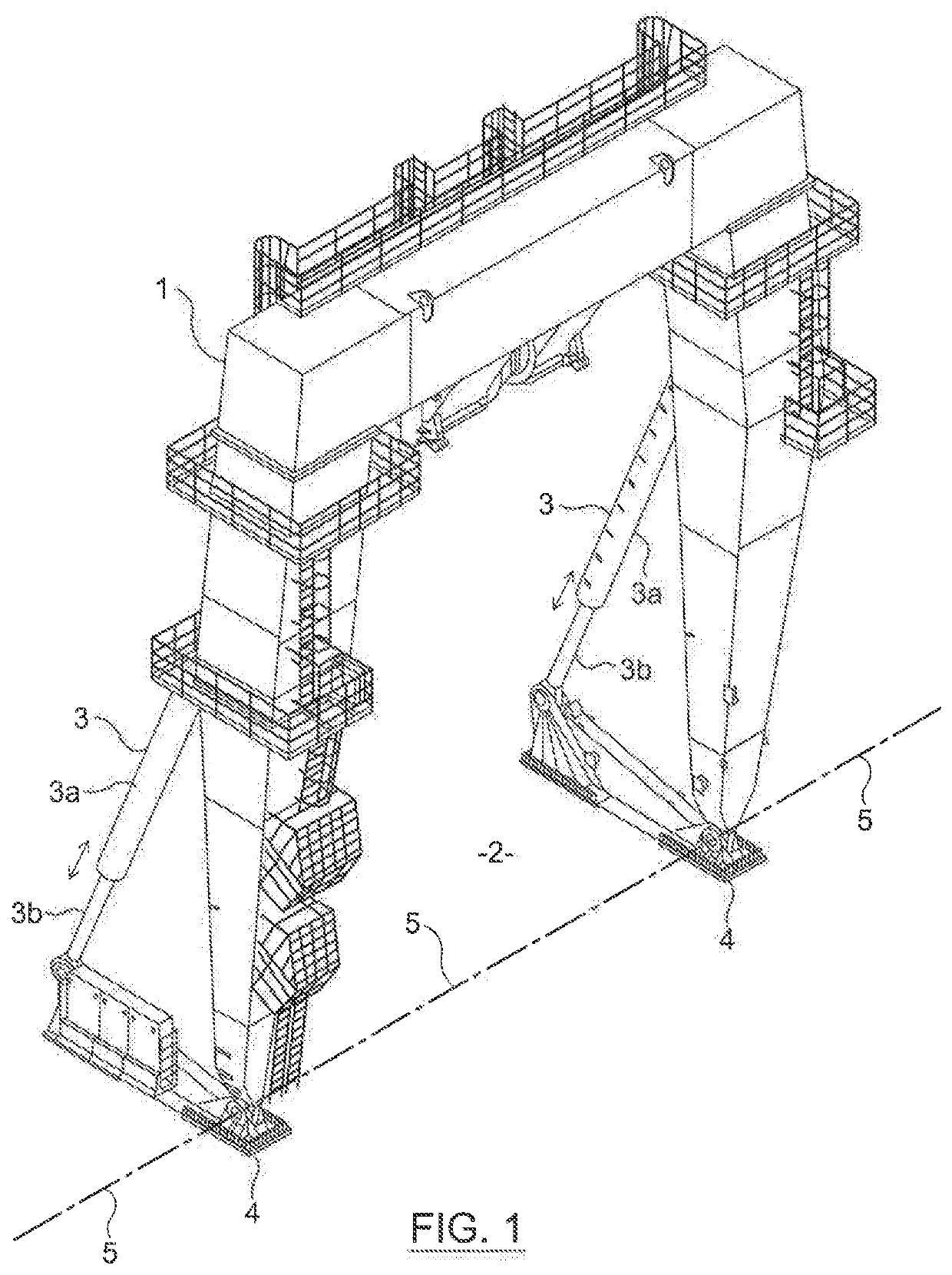
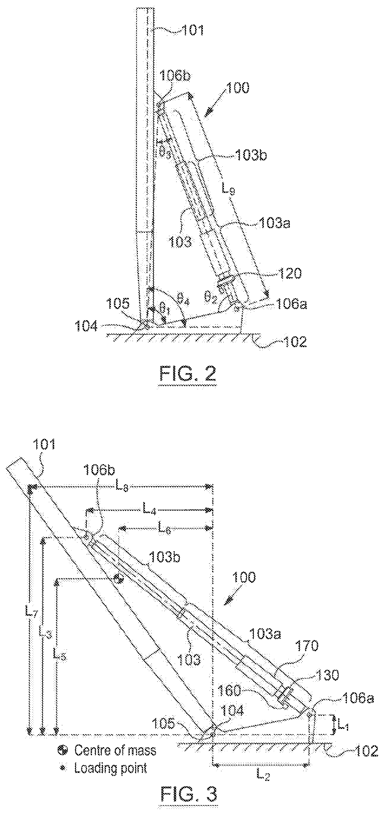
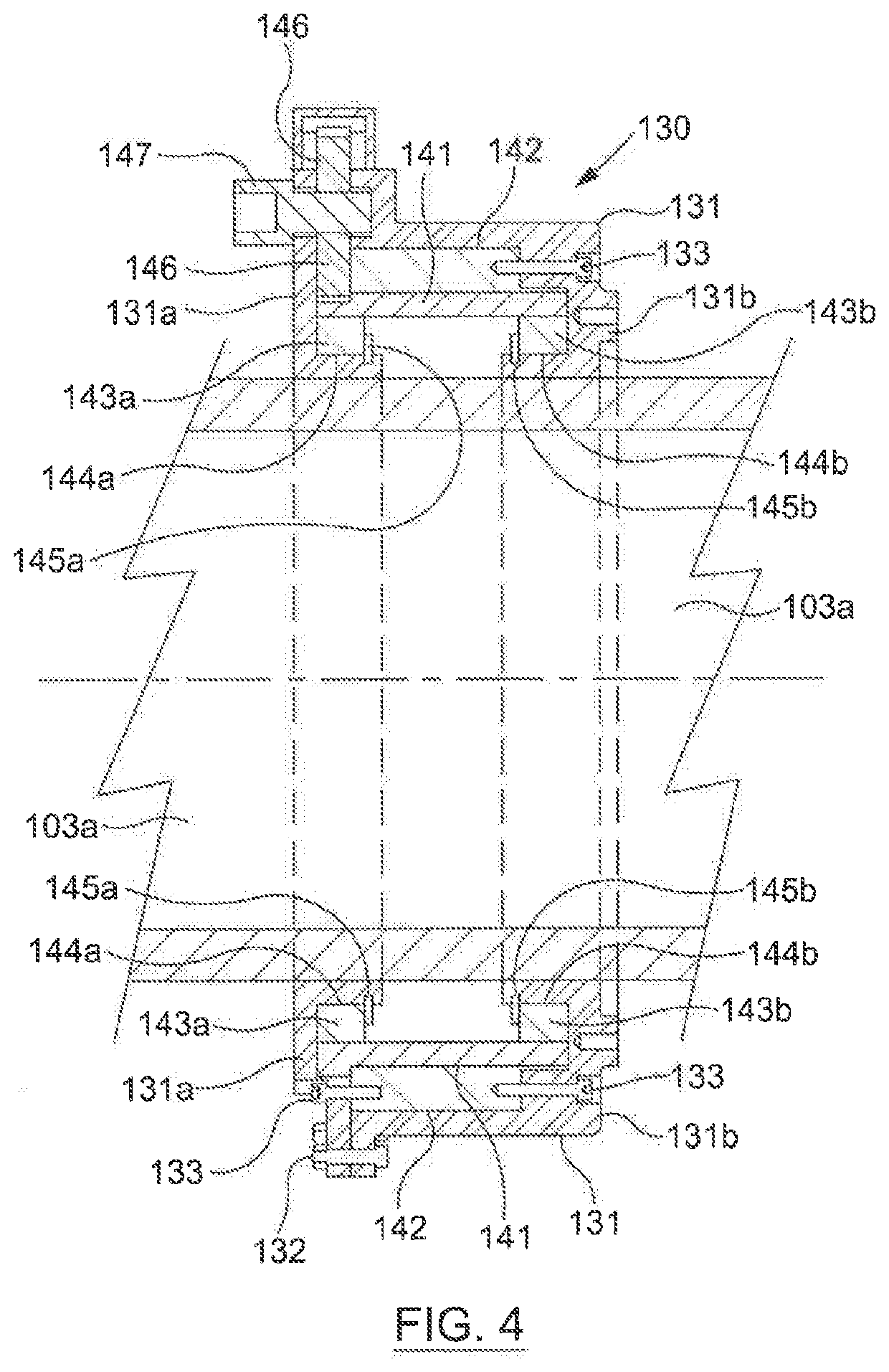
[0037]Turning first to FIGS. 2 and 3, according to an embodiment of the disclosure, an electrohydraulic device 100 is depicted which includes a hydraulic actuator in the form of an extender 103, in this example used for positioning and manipulating an A-frame 101 on a deck 102 of a vessel. The extender 103 is actuated by hydraulic fluid and operates in the example to tilt the A-frame 101 by way of axial extension of the extender 103 between the deck 102 and the A-frame 101. The extender 103 has first end 106a which is connected to the deck and a second end 106b which is connected to the leg of the A-frame 101. The first end 106a is an end of a first section 103a of the extender, and the second end 106b is an end of a second section 103b of the extender.

[0038]The first and second sections 103a, 103b are telescopically and movably coupled to one another, so that by telescoping action, the first section 103a can be axially translated relative to the second section 103b, so as to vary t...


PUM


Abstract

An electrohydraulic device includes an extender which is arranged to be actuated by hydraulic fluid, and a rotor of an electric motor, the rotor being arranged to rotate about a part of the extender. The rotor may have an annular body which encircles or surrounds part of the extender. There is also described a related method of use and a marine vessel or platform where the device may be applied.

Description

CROSS REFERENCE TO RELATED APPLICATIONS[0001]This application is a 35 U.S.C. § 371 national stage application of PCT / N02018 / 050224 filed Sep. 7, 2018 and entitled “Electrohydraulic Device, Method, and Marine Vessel or Platform”, which claims priority to European Patent Application No. 17190129.1 filed Sep. 8, 2017, each of which is incorporated herein by reference in their entirety for all purposes.STATEMENT REGARDING FEDERALLY SPONSORED RESEARCH OR DEVELOPMENT[0002]Not Applicable.FIELD OF THE DISCLOSURE[0003]This disclosure relates in particular to an electrohydraulic devices and their use such as their employment in large-scale machinery, like cranes for lifting and lowering loads,BACKGROUND[0004]The supply of hydraulic fluid to hydraulically driven machinery is generally achieved by means of hydraulic circuit. The hydraulic circuit may drive an actuator such as a piston arm arranged to extend and retract for instance in order to lift or lower a boom of a crane or the like. Hydrau...

Claims


Application Information

Patent Timeline
Patent Type & Authority Applications(United States)
IPC IPC(8): B63B27/36F15B15/08H02K7/116
CPCB63B27/36B66C23/52H02K7/116F15B15/088F15B1/26F15B15/16F15B15/18F15B2211/20515F16H1/06
Inventor BORØY, YNGVARSTRAND, THORBERGSTØL, GEIR ODD
Owner GRANT PRIDECO LP
Why Eureka
Try Eureka