Tumble dryer

Pending Publication Date: 2021-01-14
ELECTROLUX LAUNDRY SYST SWEDEN
View PDF6 Cites 2 Cited by
  • Summary
  • Abstract
  • Description
  • Claims
  • Application Information

AI Technical Summary

Benefits of technology

[0011]The drum in the tumble dryer is accessible through a door, and control of the compressor may be adapted to keep the refrigerant flow on, i.e. the compressor switched on when the door is opened, while only reducing the refrigerant flow. This implies fewer start/stop cycles of the compressor if the door e.g. is opened frequently to add or remove laundry. The refrigerant flow may however be reduced to 30-60% of the flow before the door was opened. When the door has been open a predetermined period of time, e.g. one minute, the compressor may subsequently be switched off.
[0012]The heat pump may be enclosed in an insulating shell and there may be provided an opening in the shell between the condenser and the inlet of the drum. This

Problems solved by technology

Such a tumble dryer is shown for instance in EP-3118365-A1, one problem w

Method used


Image

  • Tumble dryer
  • Tumble dryer
  • Tumble dryer

Examples


Embodiment Construction

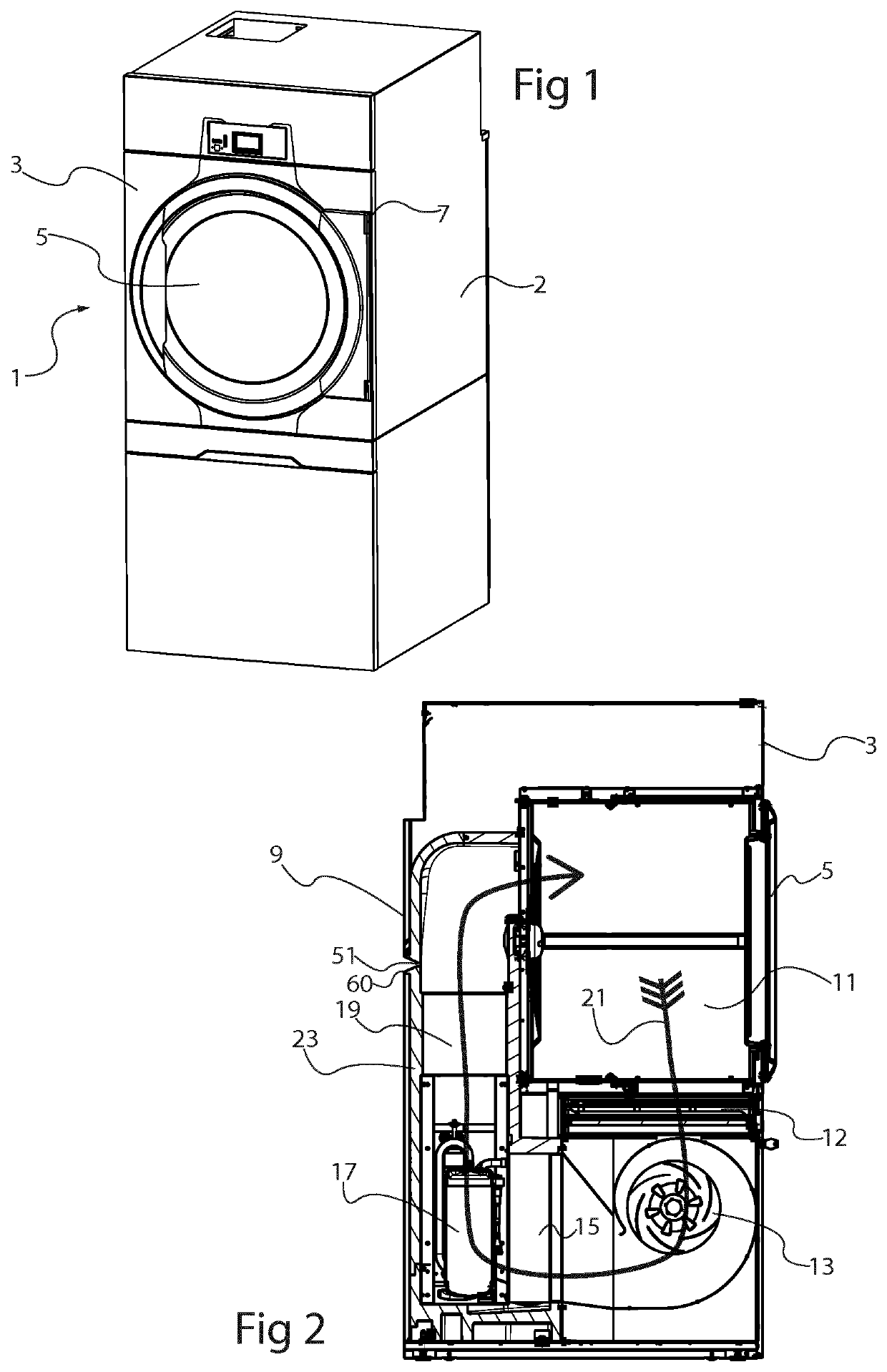
[0024]The present disclosure relates generally to a tumble dryer which is provided with a heat pump in order to achieve energy-efficient drying of laundry. An example of a tumble dryer 1 is illustrated in FIG. 1. The tumble dryer 1 has a housing 2 with a front side 3 which is provided with a door 5 or hatch, attached to the front side 3 with hinges 7, which provides access to a tumble dryer drum where wet laundry can be loaded.

[0025]FIG. 2 illustrates a cross section through a tumble dryer with a heat pump arrangement. In a heat pump tumble dryer, process air drying the laundry can circulate mostly within the outer enclosure of the tumble dryer, although some exchange of air with the outside may be allowed as will be shown. FIG. 2 illustrates in a cross section, components of such a tumble dryer as well as a process air flow path 21. As mentioned, the tumble dryer comprises a drum 11 in which wet laundry is placed. While the drum 11 rotates, a flow 21 of relatively dry process air i...


PUM


Abstract

The present disclosure relates to a tumble dryer 1 with a rotatable drum 11 and a heat pump for drying process air that enters the drum, the heat pump comprising a condenser 19, a compressor 17, and an evaporator 15. In order to improve energy efficiency, the rotatable drum comprises a circular rear wall with air inlet openings and a radial cylindrical wall with air outlet openings, the compressor 17 is adapted to be run by an inverter 29, allowing the compressor output to be varied, and the expansion 16 is controllable. This allows the heat pump arrangement to be controlled to an optimum heat pump cycle envelope.

Description

FIELD OF THE INVENTION[0001]The present disclosure relates to a tumble dryer comprising a housing, a drum in the housing being accessible from a front side of the housing and being rotatable about its center axis, a fan arrangement for producing a flow of process air passing through the drum, and a heat pump for drying the process air before entering the drum, the heat pump comprising a compressor, a condenser, an expansion valve, and an evaporator forming a refrigerant fluid loop.TECHNICAL BACKGROUND[0002]Such a tumble dryer is shown for instance in EP-3118365-A1, one problem with such tumble dryers is how to improve their energy efficiency further.SUMMARY OF THE INVENTION[0003]One object of the present disclosure is therefore to provide a tumble dryer with improved efficiency. This object is achieved by means of a tumble dryer as defined in claim 1. More specifically, the rotatable drum comprises a circular rear wall with air inlet openings and a radial cylindrical wall with air o...

Claims


Application Information

Patent Timeline
IPC IPC(8): D06F58/20D06F58/22D06F58/04D06F58/38
CPCD06F58/206D06F58/22D06F2105/26D06F58/38D06F58/04D06F58/20D06F2103/50D06F2103/40
Inventor BRISJÖ, JOHANNILSSON, MARTINPERSSON, GUNNAR INGEMAR
Owner ELECTROLUX LAUNDRY SYST SWEDEN
Why Eureka
Try Eureka