A rolling assembly

a technology of rolling assembly and rim, which is applied in the direction of tire beads, vehicle components, and without separate inflatable inserts, etc., can solve the problems of unsatisfactory steering improvement and maintenance, and achieve satisfactory interior noise performance and/or the ability to withstand curb impact. , the effect of improving the steering of the vehicl

Inactive Publication Date: 2021-01-21
MICHELIN & CO CIE GEN DES ESTAB MICHELIN
View PDF5 Cites 0 Cited by
  • Summary
  • Abstract
  • Description
  • Claims
  • Application Information

AI Technical Summary

Benefits of technology

[0038]According to the arrangements described above, it is possible to provide improvement on steering o...

Problems solved by technology

However with these solutions steering improvement is not yet satisfactory while main...

Method used


Image

  • A rolling assembly
  • A rolling assembly

Examples


Embodiment Construction

[0045]Preferred embodiments of the present disclosure will be described below referring to the drawings.

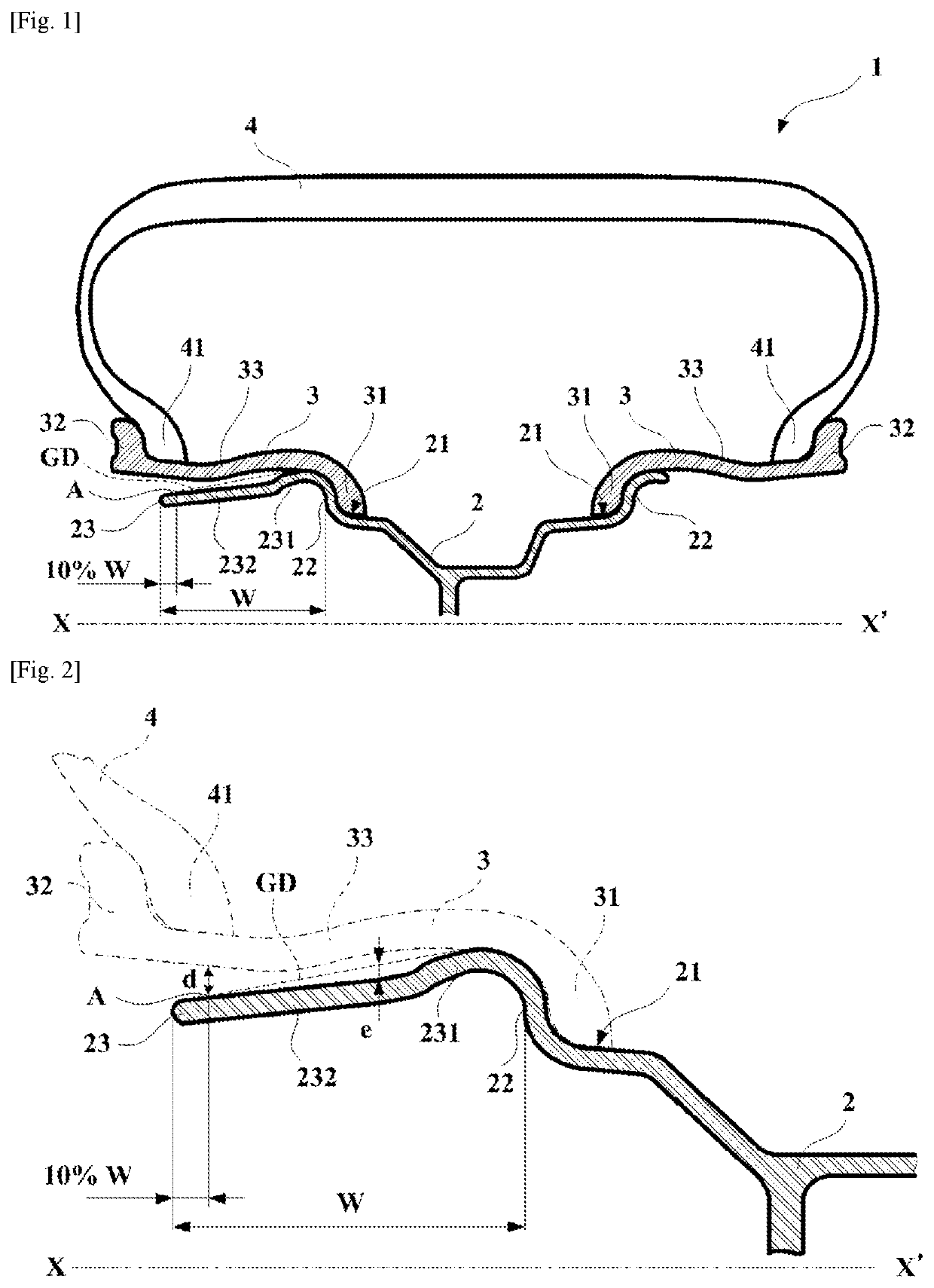
[0046]A rolling assembly 1 according to a first embodiment of the present disclosure will be described referring to FIGS. 1 and 2.

[0047]FIG. 1 is a schematic sectional view of a rolling assembly according to a first embodiment of the present disclosure. FIG. 2 is a schematic sectional view of a rim of the rolling assembly according to the first embodiment of the present disclosure.

[0048]The rolling assembly 1 is a rolling assembly having a rotation axis XX′ where X is a direction intended to be outside when the rolling assembly 1 being mounted onto a vehicle, thus X′ is a direction intended to be inside when the rolling assembly 1 being mounted onto a vehicle, and comprising a rim 2 having two rim seats 21 being axially outwardly extended by rim flanges 22, two adapters 3 and a tire 4 having two beads 41, each the adapter 3 providing the connection between one of the bead 41 and t...


PUM


Abstract

The rolling assembly has a rotation axis and a rim having rim seats and flanges, an adapter and a tire having beads. The adapter provides the connection between one of the beads and the rim. The rim comprises a portion of a width W extending outwardly from the flange and a connecting introduction portion and a body. The body has a point A that is 10% of W axially inward from an axially outermost of the body or from an axially outermost of the adapter. The portion creates a virtual straight line GD between an innermost of the connecting introduction portion and the point A. The portion and the adapter has a radial distance d at the point A. The body has a maximum radial distance e from the virtual straight line GD at axially inward from the point A, and the body has no contact with the adapter.

Description

CROSS-REFERENCE TO RELATED APPLICATIONS[0001]This application claims priority to and the benefit of PCT Patent Application No. PCT / JP2018 / 013628, filed Mar. 30, 2018, entitled “A ROLLING ASSEMBLY.”BACKGROUND OF THE INVENTION1. Technical Field[0002]The present disclosure relates to a rim for a vehicle including a seat for receiving a tire bead is radially floating. The present disclosure relates in particular systems containing flexible adapter inserted between a tire bead and a rim.[0003]A tire, a rim, an adapter, referred to in the present disclosure, objects are usually described by a representation in a meridian plane, that is to say a plane containing a rotation axis (an axis of rotation) of the tire. All these products (a tire, a rim and an adapter) are objects having geometry of revolution relative to their axis of rotation.2. Related Art[0004]A tire currently used these days mainly comprises a tread intended to provide contact with ground, this tread generally being reinforce...

Claims


Application Information

Patent Timeline
IPC IPC(8): B60B21/12B60C15/024
CPCB60B21/12B60B21/10B60C15/024B60C15/02B60B25/045B60B25/10B60B25/12B60C5/16B60C15/0209
Inventor BABAUD, JACQUESFUKUDA, KENJI
Owner MICHELIN & CO CIE GEN DES ESTAB MICHELIN
Why Eureka
Try Eureka