Push-pull handle module

a technology of push-pull and handle, which is applied in the field of mechanical modules, can solve the problems of spring plate portion interference, server pulling out, misjudgment of operation state, etc., and achieve the effect of convenience and intuition in operation

Inactive Publication Date: 2021-02-04
PEGATRON
View PDF0 Cites 1 Cited by
  • Summary
  • Abstract
  • Description
  • Claims
  • Application Information

AI Technical Summary

Benefits of technology

[0016]Based on the above, in the push-pull handle module of the invention, the protrusion of the handle is slidably disposed in the slot of the bracket, so that the handle can pivot relative to the bracket, and move along the slot to rotate between the first position and the second position relative to the bracket. When the handle is in the first position, the locking portion can lock the rack to fix the electronic module in the rack. When the handle is in the second position, the locking portion does not lock the rack, so that the user can pull the electronic module in the rack out of the rack through the handle. In this way, the push-pull handle module of the invention can provide convenience and intuition in operation to the user.

Problems solved by technology

Therefore, with the conventional push-pull handles, it is difficult to identify the operation state intuitively, which may cause a misjudgement on the operation state and the server gets pulled out by mistake.
When the handle is in the first position, the spring plate portion interferes with the bracket to fix the handle to the bracket.

Method used


Image

  • Push-pull handle module
  • Push-pull handle module
  • Push-pull handle module

Examples


Embodiment Construction

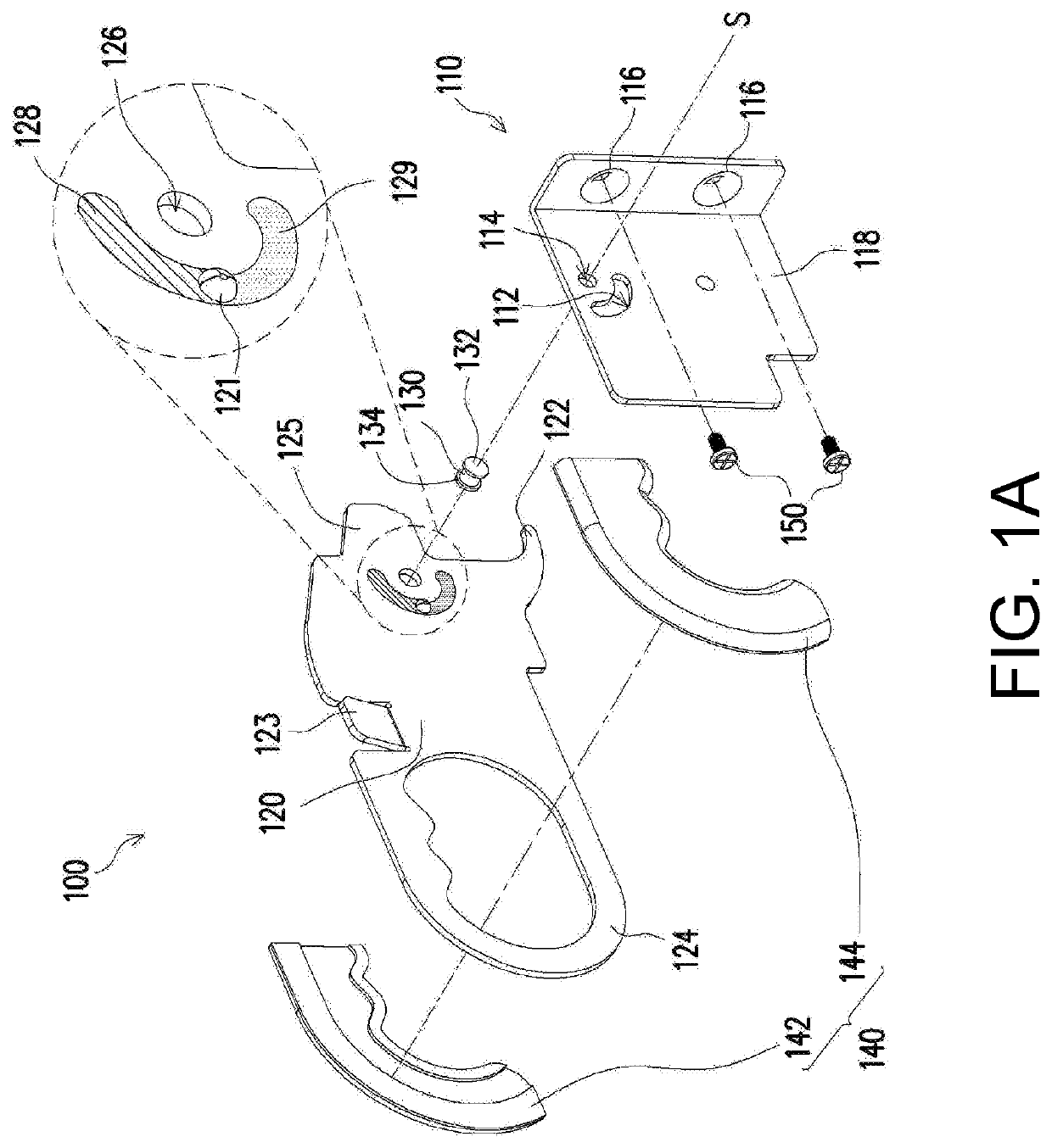
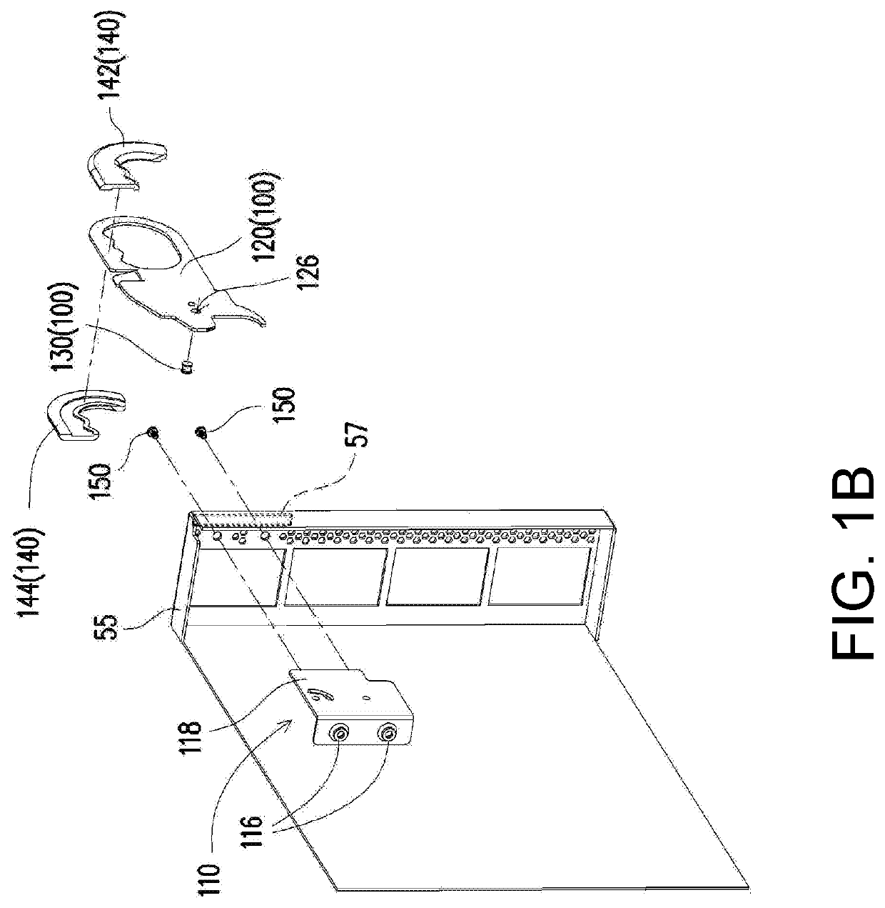
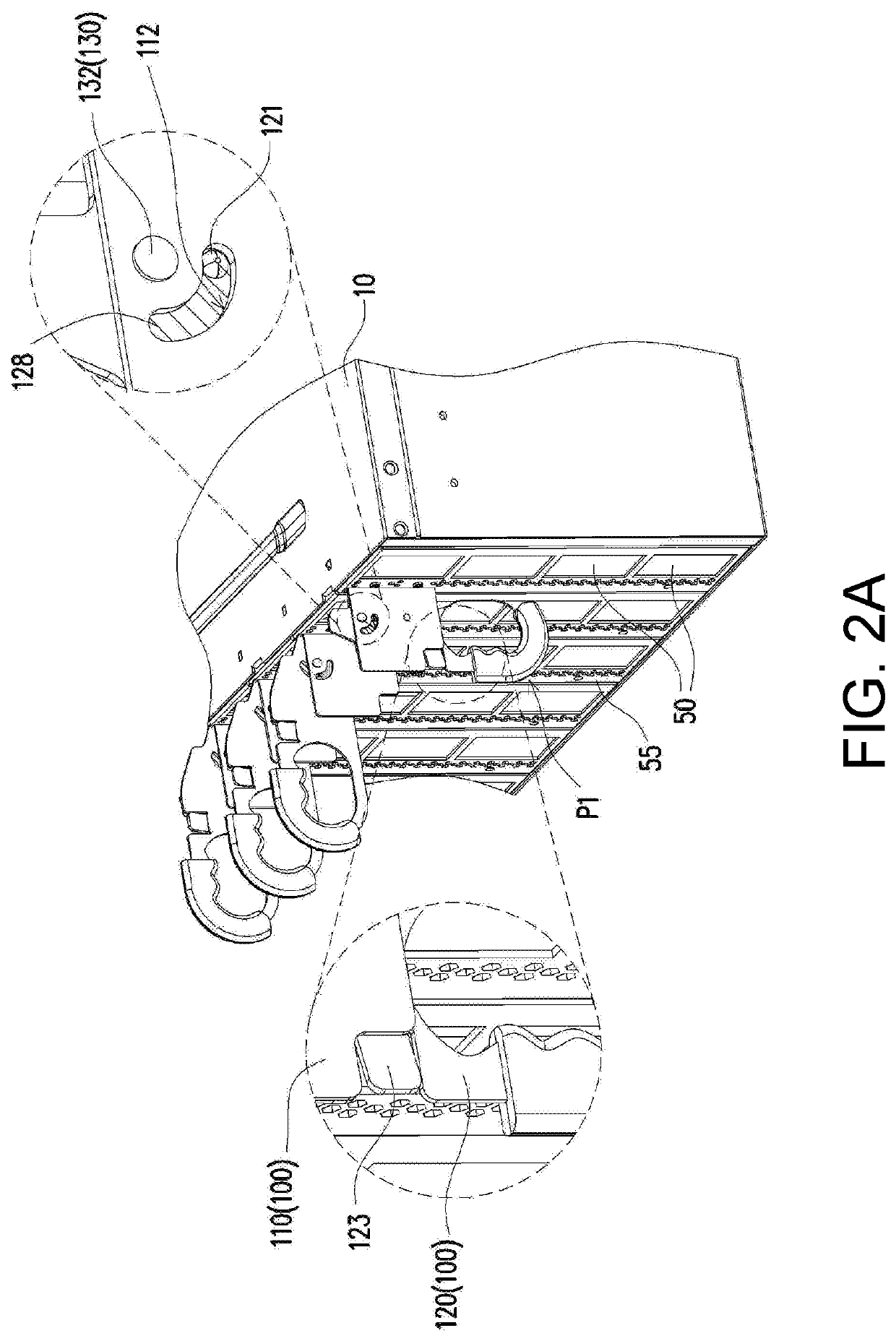
[0024]FIG. 1A is a three-dimensional exploded view of a push-pull handle module according to an embodiment of the invention. FIG. 1B is a three-dimensional exploded view of the push-pull handle module in FIG. 1A from another angle of view and a case of an electronic module. FIG. 2A to FIG. 2C are three-dimensional views of the push-pull handle module in FIG. 1A locking an electronic module in a rack, with a handle rotating between a first position and a second position. FIG. 3 is a partial three-dimensional cross-sectional view of the push-pull handle module in FIG. 1A locking an electronic module in a rack. FIG. 4 is a partial three-dimensional cross-sectional view of the push-pull handle module in FIG. 1A abutting against an electronic module. For ease of description, FIG. 3 omits to show the electronic module.

[0025]First, referring to FIG. 1A, FIG. 1B, FIG. 2A, and FIG. 3, in the present embodiment, a push-pull handle module 100 is adapted to lock at least one electronic module i...


PUM


Abstract

A push-pull handle module is adapted to lock at least one electronic module in a rack. The push-pull handle module includes a bracket and a handle. The bracket is fixed to the at least one electronic module and includes a slot. The handle is pivotally connected to the bracket and includes a protrusion and a locking portion. The protrusion is slidably disposed into the slot of the bracket. When the handle is in a first position, the locking portion locks rack the at least one electronic module in the rack. When the handle rotates from the first position to a second position relative to the bracket, the locking portion does not lock the at least one electronic module.

Description

CROSS-REFERENCE TO RELATED APPLICATION[0001]This application claims the priority benefit of Taiwan application serial no. 108127563, filed on Aug. 2, 2019. The entirety of the above-mentioned patent application is hereby incorporated by reference herein and made a part of this specification.BACKGROUNDTechnical Field[0002]The disclosure relates to a mechanical module, and in particular, to a push-pull handle module.Description of Related Art[0003]Conventional push-pull handles only have a hooking function. Therefore, when a server is placed in a rack, a handle needs to be additionally disposed to pull the server out of the rack. Moreover, the conventional push-pull handles do not have a limiting mechanism to limit angles while opening and closing, and a user can only pull the server out of the rack after confirming, by the observation or the feeling of a movement, that the hooking portion is detached. In addition, a user is aware of whether the server is operating only through a sign...

Claims


Application Information

Patent Timeline
Patent Type & Authority Applications(United States)
IPC IPC(8): H05K7/14
CPCH05K7/1489H05K7/1401H05K7/1415
Inventor YE, LONG-SINGHUANG, YAO-HSIEN
Owner PEGATRON
Why Eureka
Try Eureka