Monitoring device applied to printer

A monitoring device and printer technology, applied in the direction of digital output to the printing unit, etc., can solve the problems of inconsistent economic benefits, troublesome operation process, waste of resources of printer manufacturers, etc., and achieve the effect of intuitive and convenient operation and low cost

Inactive Publication Date: 2016-02-10
SHAANXI EYINHE ELECTRONICS
View PDF0 Cites 1 Cited by
  • Summary
  • Abstract
  • Description
  • Claims
  • Application Information

AI Technical Summary

Problems solved by technology

[0005] Although the existing technology that the after-sales service personnel carry the notebook computer with them has the same effect as a monitor, for printer manufacturers with a large number of customers, it is necessary to pre-order an appropriate number of notebook computers for the after-sales service personnel to prepare for all after-sales service personnel. The need for service personnel to work at the same time, which creates an excessive cost burden
Moreover, actually performing simple functions such as receiving data from the host (computer or printer) and writing printer-related drivers, using a powerful notebook computer not only does not meet economic benefits, but also causes waste of resources for printer manufacturers, thereby improving printer performance. Manufacturer's maintenance costs
[0006] In addition, during the actual operation process of updating the printer driver, the after-sales service personnel must go through several procedures such as starting the notebook computer, selecting the corresponding application program, extracting data, and writing the corresponding driver program to the printer. Not only is the operation process cumbersome, Time-consuming, not intuitive enough, and it is easy to cause errors due to factors such as human error and conflicts between various computing programs on notebook computers, such as firewalls or anti-virus software blocking data transmission, etc.

Method used


Image

  • Monitoring device applied to printer
  • Monitoring device applied to printer

Examples


Embodiment Construction

[0017] In order to further illustrate the present invention, further describe below in conjunction with accompanying drawing:

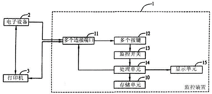
[0018] Such as figure 1 As shown, the monitoring device 1 is used to monitor the printer 3 connected to the electronic device 2, and its working principle is: first, the electronic device 2 sends data to the printer 3, and the monitor 1 also receives the data sent by the electronic device 2 as a slave device , then, when the printer 3 receives the command of the electronic device 2, it feeds back the contact exchange signal to the electronic device 2, and determines that the communication between the electronic device 2 and the printer 3 starts. At this time, the data received by the monitor 1 as a slave device It is the same as the data received by the electronic device 2 . During the entire communication process between the electronic device 2 and the printer 3, the monitor 1 only receives data without sending any feedback signal to it. Only when ...


PUM


Abstract

The invention discloses a monitoring device applied to a printer. The monitoring device applied to the printer comprises a memory unit, a plurality of connecting ports, a control unit, a processing unit and a display unit, and is characterized in that at least drive software of the printer is pre-stored in the memory unit, and the memory unit is one of a data buffer memory or a data memory; the plurality of connecting ports are respectively and electrically connected with electronic equipment and the printer, and each of the plurality of connecting ports is one selected from a group consisting of parallel connecting ports, serial connecting ports, USB connecting ports, network connecting ports or wireless network connecting ports. The monitoring device is specially used for monitoring the printer connected with the electronic equipment, the processing unit with a proper operation function and other units can be selectively used, thus the cost is comparatively lower and the operations of monitoring the printer and updating the drive program of the printer are more intuitive, more convenient, quicker and more reliable.

Description

technical field [0001] The invention relates to a monitoring device applied to a printer. Background technique [0002] Among all computer peripheral devices, the probability of printer failure is usually high, and the reasons for the failure are also varied. If you do not have enough failure information, it is impossible to repair it. Therefore, keep the communication backup data for judging the failure information. That is, it is particularly important for maintenance work. [0003] At present, the fault analysis method commonly used by printer manufacturers is to extract the communication backup data between the computer and the printer through the monitor, and then the after-sales service personnel of the printer manufacturer extract and analyze the backup data to judge the fault condition of the printer. The above-mentioned printer communicates with the computer through the connection port. Currently, the commonly used printer connection ports include parallel connecti...

Claims


Application Information

Patent Timeline
Patent Type & Authority Applications(China)
IPC IPC(8): G06F3/12
Inventor 李洋陈刚杨树峰李涛肖剑林李华清
Owner SHAANXI EYINHE ELECTRONICS
Why Eureka
Try Eureka