Eureka AIR delivers breakthrough ideas for toughest innovation challenges, trusted by R&D personnel around the world.

Socket for Upper Extremity Prosthesis

Active Publication Date: 2021-02-18
UNLTD TOMORROW INC
View PDF0 Cites 0 Cited by
  • Summary
  • Abstract
  • Description
  • Claims
  • Application Information

AI Technical Summary

Benefits of technology

The patent describes a socket for coupling a prosthetic upper extremity to a residual limb of a user. The socket has a proximal portion and a distal portion, with a joint that connects them. The joint is a polycentric joint that allows for rotation between the two portions. The distal portion has a coupling portion for receiving the residual limb and a linking portion for coupling to the prosthetic upper extremity. The socket may also include a tensioning system to secure the prosthetic to the user. The technical effects of the patent include improved stability and comfort for users with prosthetic upper extremities.

Problems solved by technology

Conventional upper extremity prosthetic devices can be expensive and can take a long time to produce, which may make them unsuitable or undesirable for many uses.
This generally means that the fingers have a predetermined motion path and are unable to conform to objects.
The socket creation may result in even more time and even more cost to the prosthesis.
As a result, many child amputees do not use these existing market devices.
The conventional socket system is generally created by hand and is manual labor intensive.
In order to provide a more natural appearance of the prosthesis, custom silicon gloves have been created to match the user's skin tone, but this can dramatically increase costs and the glove often wears and breaks down rapidly.

Method used


Image

  • Socket for Upper Extremity Prosthesis
  • Socket for Upper Extremity Prosthesis
  • Socket for Upper Extremity Prosthesis

Examples


Embodiment Construction

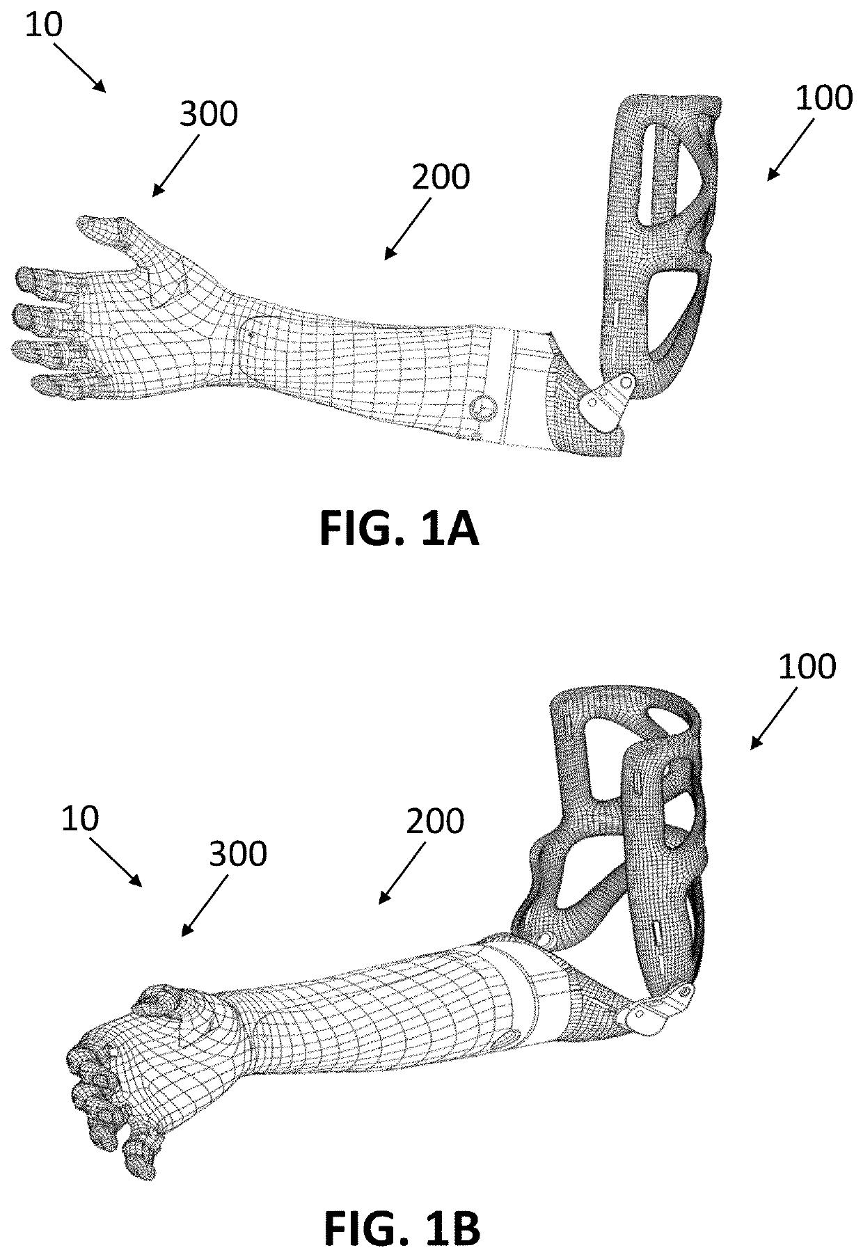
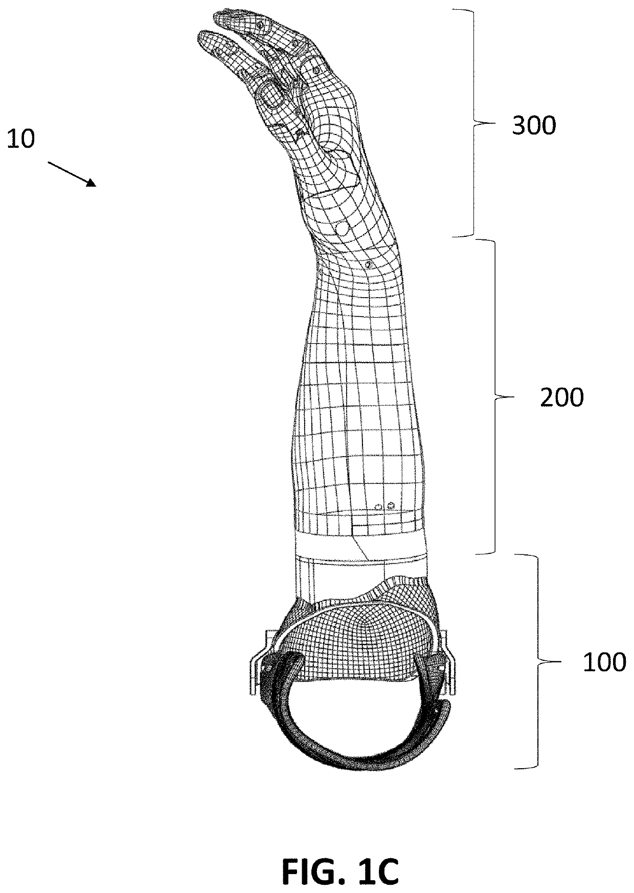
[0062]FIGS. 1A-C show an embodiment of a prosthetic upper extremity 10 for use in humans. Generally, prosthetic upper extremity 10 may include a socket 100, a prosthetic forearm 200, and a prosthetic hand 300, each of which is described in greater detail below. It should be understood that the illustrated prosthetic upper extremity 10 is for a right side of a user, but a substantially identical prosthetic upper extremity could be used for the left side of a user, with the features of the left side prosthetic extremity being substantially a mirror image of the illustrated right side prosthetic upper extremity 10.

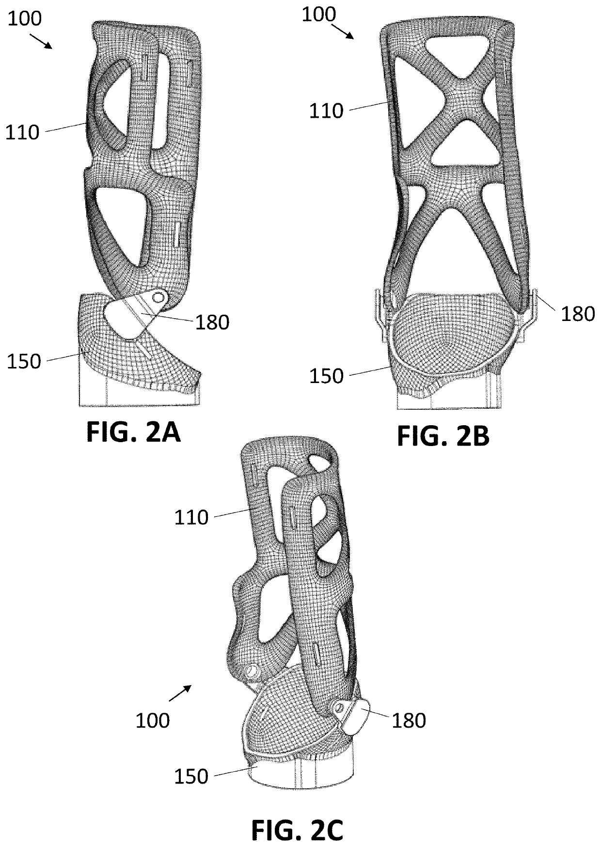
[0063]FIGS. 2A-C show an embodiment of socket 100, which may generally function to couple the user's residual limb to the prosthetic forearm 200. Generally, socket 100 is a rigid member that matches the shape and contours of the user's residual limb, and may be attached to the residual by a compression fit or other suitable mechanism. In the illustrated embodiment, socket 100...


PUM


Abstract

A socket may be for coupling a prosthetic upper extremity to a residual limb of a user. The socket may include a proximal socket portion and a distal socket portion coupled to the proximal socket portion by a polycentric joint. The polycentric joint may include a plate having a first end coupled to the proximal socket portion via a first fastener, and a second end coupled to the distal socket portion via a second fastener. The proximal socket portion may be rotatable relative to the distal socket portion about a first axis passing through the first fastener and about a second axis passing through the second fastener.

Description

CROSS-REFERENCE TO RELATED APPLICATIONS[0001]This application claims the benefit of the filing date of U.S. Provisional Patent Application No. 62 / 887,797, filed Aug. 16, 2019, the disclosure of which is hereby incorporated by reference herein.BACKGROUND OF THE DISCLOSURE[0002]The present disclosure is directed to sockets for use with prostheses, including upper extremity prostheses.[0003]Prosthetic arms have been available for use, for example by amputees, for many years. More recently, mechanical and robotic components have been introduced into prosthetic arms to provide a wide range of functionality to the prosthetic arm, for example, with individual finger joints with various mechanisms of control, including based on the user's muscle control.[0004]Conventional upper extremity prosthetic devices can be expensive and can take a long time to produce, which may make them unsuitable or undesirable for many uses. Some advanced electric hands on the market use a linkage mechanism to mo...

Claims


Application Information

Patent Timeline
IPC IPC(8): A61F2/80A61F2/58A61F2/72
CPCA61F2/80A61F2002/543A61F2/72A61F2/582A61F2002/503A61F2/78
Inventor LACHAPPELLE, EASTON J.MALCOCI, ALEXANDRU STEFAN
Owner UNLTD TOMORROW INC
Why Eureka
Eureka Blog
Learn More