Image capture device, system, method for controlling image capture device, and non-transitory computer-readable storage medium

Active Publication Date: 2021-03-25
CANON KK
View PDF0 Cites 2 Cited by
  • Summary
  • Abstract
  • Description
  • Claims
  • Application Information

AI Technical Summary

Benefits of technology

[0007]A technology is provided that enables a detection region to be set at a position that is set by a user even if a PTZ value of a captured image when the detection region is set differs from a PTZ value of a PTZ preset designated by detection rule settings.

Problems solved by technology

In this case, if the current PTZ value for capturing an image when setting a detection region in a captured image displayed on a UI screen differs from the PTZ value of a PTZ preset designated by detection rule settings, a problem arises in that the detection region is set at a position different from the position that is set on the UI screen.

Method used


Image

  • Image capture device, system, method for controlling image capture device, and non-transitory computer-readable storage medium
  • Image capture device, system, method for controlling image capture device, and non-transitory computer-readable storage medium
  • Image capture device, system, method for controlling image capture device, and non-transitory computer-readable storage medium

Examples


first embodiment

[0023]A first embodiment of the invention will be described below.

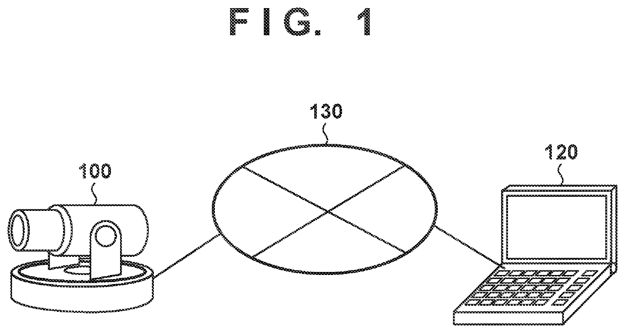
[0024]Firstly, a system configuration according to the present embodiment will be described with reference to FIG. 1. FIG. 1 is a diagram showing an example of a system configuration including a monitoring camera 100. The monitoring camera 100 and a client device 120 are communicably connected to each other via a network 130. The client device 120, serving as an external device, transmits, to the monitoring camera 100, control commands such as commands to give instructions of create, edit, and delete a PTZ preset, and commands to give instructions to create, edit, and delete a detection rule in object detection. The monitoring camera 100 creates, edits, and deletes a PTZ preset, and also creates, edits, and deletes a detection rule in accordance with the commands, and transmits responses to the commands to the client device 120.

[0025]The monitoring camera 100 is, for example, an image capture device that is installed ...

second embodiment

[0068]Next, a second embodiment of the present invention will be described. The system configuration, the functional configuration, the hardware configuration, and so on in the present embodiment are the same as those described with reference to FIGS. 1 to 6 in the first embodiment, and a description thereof is omitted accordingly.

[0069]The details of the detection rule editing processing in step S502 in FIG. 5 according to the present embodiment will be described with reference to FIG. 7. First, in step S701, the communication unit 106 of the monitoring camera 100 receives a ModifyRules command from the client device 120. The ModifyRules command includes designation of PresetToken as mentioned above. In the following step S702, the control unit 101 of the monitoring camera 100 specifies, in the PTZ preset setting table 410, a PTZ preset setting that is designated by PresetToken included in the received ModifyRules command. Then, the control unit 101 compares a PTZ value registered ...

third embodiment

[0079]Next, a third embodiment of the invention will be described. The system configuration, the functional configuration, the hardware configuration, and so on in the present embodiment are the same as those described with reference to FIGS. 1 to 6 in the first embodiment, and a description thereof is omitted accordingly.

[0080]The details of the detection rule editing processing in step S502 in FIG. 5 according to the present embodiment will be described with reference to the flowchart in FIG. 8. In step S801, the communication unit 106 of the monitoring camera 100 receives a ModifyRules command from the client device 120. The ModifyRules command includes designation of PresetToken as mentioned above.

[0081]In the following step S802, the control unit 101 of the monitoring camera 100 specifies, in the PTZ preset setting table 410, a PTZ preset setting that is designated by PresetToken included in the received ModifyRules command. Then, the control unit 101 compares a PTZ value regis...


PUM


Abstract

An image capture device comprising, an image capture unit, an image-capture control unit controlling PTZ, a storage unit storing setting information including a set value of the PTZ for capturing a predetermined region, and region information specifying a detection region for an object, a reception unit receiving, from an information processing device, an editing instruction to edit the region information including information designating the setting information, a determination unit determining whether or not the set value of the PTZ in first setting information matches a current set value of the PTZ, and a processing unit updating the set value of the PTZ in the first setting information with the current set value of the PTZ if the set value of the PTZ does not match the current set value of the PTZ.

Description

BACKGROUND OF THE INVENTIONField of the Invention[0001]The present disclosure relates to an image capture device, a system, a method for controlling an image capture device, and a non-transitory computer-readable storage medium.Description of the Related Art[0002]A monitoring camera with a pan-tilt-zoom (PTZ) mechanism is provided with a function of registering a PTZ position as a preset in accordance with an instruction from a user, and moving to the PTZ position registered as a PTZ preset in accordance with an instruction. Also, the monitoring camera is provided with a function of, for example, detecting an object in a captured image. The user can operate a user interface (UI) on a screen that displays an image received by an information processing device from the monitoring camera, and set a detection region that indicates a region to perform detection in the screen, and detection rules including a detection rule name or the like.[0003]Patent Document 1 discloses a technology by ...

Claims


Application Information

Patent Timeline
Patent Type & Authority Applications(United States)
IPC IPC(8): H04N5/232
CPCH04N5/23225H04N5/23206H04N5/23296H04N5/23299H04N23/661H04N23/69H04N23/695H04N23/617
Inventor HONJO, WATARU
Owner CANON KK
Why Eureka
Try Eureka