A procedure and orbital implant for orbit anchored bone affixation of an eye prosthesis

a bone affixing and eye prosthesis technology, applied in the field of procedure and orbital implant for orbit anchored bone affixation of an eye prosthesis, can solve the problems of loss of binocular vision and hence depth perception, loss of eyeball, eyelid or surrounding muscles, etc., and achieves the effect of reducing or eliminating guesswork in proper positioning, high level of accuracy, and greater confidence in social interactions

Active Publication Date: 2021-04-15
TMJ ORTHOPAEDICS PTY LTD
View PDF16 Cites 7 Cited by
  • Summary
  • Abstract
  • Description
  • Claims
  • Application Information

AI Technical Summary

Benefits of technology

[0013]As such, the present orbital implant attaches conformingly and discreetly directly to the orbit rim (such as the supero-lateral aspect of the orbit at the zygomatic and frontal bone margin) such that the transdermal abutments orientate convergently in towards the orbit from an inner edge of the baseplate. A prosthetic eye is then attached at a circumferential edge thereof to each of the inwardly convergent transdermal abutments by magnets, clips or screws or the like to securely and discreetly locate the prosthetic eye within the orbit.
[0027]Furthermore a bone anchored eye prosthesis avoids patients having to rely on spectacles to support the prosthesis and provides securer attachment, ultimately offering the patient greater when social interactions confidence.

Problems solved by technology

Trauma, disease and developmental deformities may result in the loss of the eyeball, eyelids or surrounding muscles of the eye.
A missing eye results in loss of binocular vision and hence depth perception.
Aesthetic and psychological stigma of a missing eye may lead to social seclusion and depression.
Unfortunately, spectacles have problems of micro-movement and skin irritation.
However, because the bone thickness at the orbit rim is very thin, the screws must be extremely short or placed more securely elsewhere.
Also, the placement of the screws is often reliant on guess work.

Method used


Image

  • A procedure and orbital implant for orbit anchored bone affixation of an eye prosthesis
  • A procedure and orbital implant for orbit anchored bone affixation of an eye prosthesis
  • A procedure and orbital implant for orbit anchored bone affixation of an eye prosthesis

Examples


Embodiment Construction

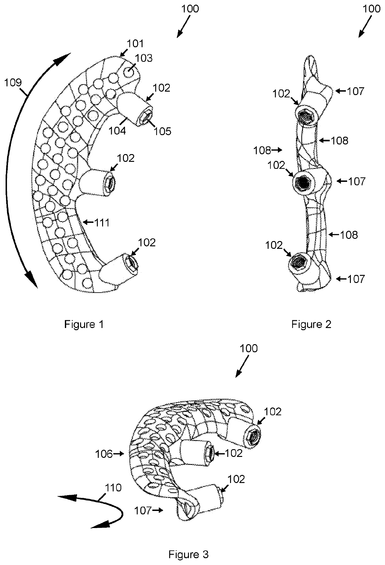
[0063]FIGS. 1-3 show an orbital implant 100 for bone anchored affixation of an eye prosthesis.

[0064]The implant 100 comprises a base plate 101, preferably of resilient biocompatible material, such as titanium.

[0065]The baseplate 101 is shaped to comprise an orbital radius curvature 109 and an orbit rim curvature 110 so as to conform to the bone of the rim an adjacent wall of the orbit for affixation thereto in the manner described herein.

[0066]The baseplate 101 may comprise a plurality of microfixation apertures 103 which may be substantially evenly spaced across the baseplate 101 in the manner illustrated.

[0067]The implant 101 further comprises a plurality of transdermal abutments 102 which are located at an inner edge 111 of the baseplate 101. The transdermal abutments 102 are located and sized so as to protrude convergently transdermally into the interior of the orbit for the affixation of an eye prosthesis thereto.

[0068]In the embodiment shown, the transdermal abutments 102 comp...


PUM


Abstract

An orbital implant adapted for attachment to the very thin bone at the orbit rim (502), such as the zygomatic and frontal bone margin at the supero-lateral aspect (501) of the orbit (503), for the attachment of an eye prosthesis directly to distal ends of inwardly convergently orientated transdermal abutments. The orbital implant has a baseplate (100) having an orbit radius curvature and an orbit rim curvature and a plurality of microfixation apertures therethrough and the plurality of transdermal abutments are located at an inner edge of the baseplate (100).

Description

FIELD OF THE INVENTION[0001]This invention relates generally to a procedure and orbital implant for orbit anchored bone affixation of an eye prosthesis.BACKGROUND OF THE INVENTION[0002]Trauma, disease and developmental deformities may result in the loss of the eyeball, eyelids or surrounding muscles of the eye. A missing eye results in loss of binocular vision and hence depth perception. Aesthetic and psychological stigma of a missing eye may lead to social seclusion and depression.[0003]Currently, facial prosthetic laboratories fabricate life-like glass eyes with surrounding eyelids of silicon rubber which can be held in place with a modified pair of spectacles. Unfortunately, spectacles have problems of micro-movement and skin irritation.[0004]As such, alternative arrangements may comprises a stand-alone orbital prosthesis that is directly anchored to the underlying facial bone with miniature osseointegrated titanium screws.[0005]However, because the bone thickness at the orbit ri...

Claims


Application Information

Patent Timeline
Patent Type & Authority Applications(United States)
IPC IPC(8): A61F2/28A61F2/14
CPCA61F2/2875A61F2/141A61F2002/30952A61F2220/0008A61F2002/2878A61F2/78A61F2002/505A61F2310/00023A61F2002/0081
Inventor DIMITROULIS, GEORGE
Owner TMJ ORTHOPAEDICS PTY LTD
Why Eureka
Try Eureka