Adaptive Work-Stop

Inactive Publication Date: 2021-04-15
KENNER DANIEL R
View PDF0 Cites 0 Cited by
  • Summary
  • Abstract
  • Description
  • Claims
  • Application Information

AI Technical Summary

Benefits of technology

The invention provides a work-holding-collet with a quickly exchangeable and accurate work stop member. The work-stop member is attached to the collet body and can be positioned at different locations to block the insertion of a workpiece. The work-stop member can be a rod or a tube stop, and it is secured in a fixed position using a setscrew. The invention also provides a solution for handling the special problem of using a tee-square stop by centering the shank and stabilizing the shaft. The work-holding-collet is adaptable to different work stop-rod sizes, and the tube stop can be positioned for different reception holes in the tube wall.

Problems solved by technology

The problem that arises is that a small offset from perfect centering of the shank in the passageway of the work-stop body is translated into a wobble of the broad head of the tee-square stop.

Method used


Image

  • Adaptive Work-Stop
  • Adaptive Work-Stop
  • Adaptive Work-Stop

Examples


first embodiment

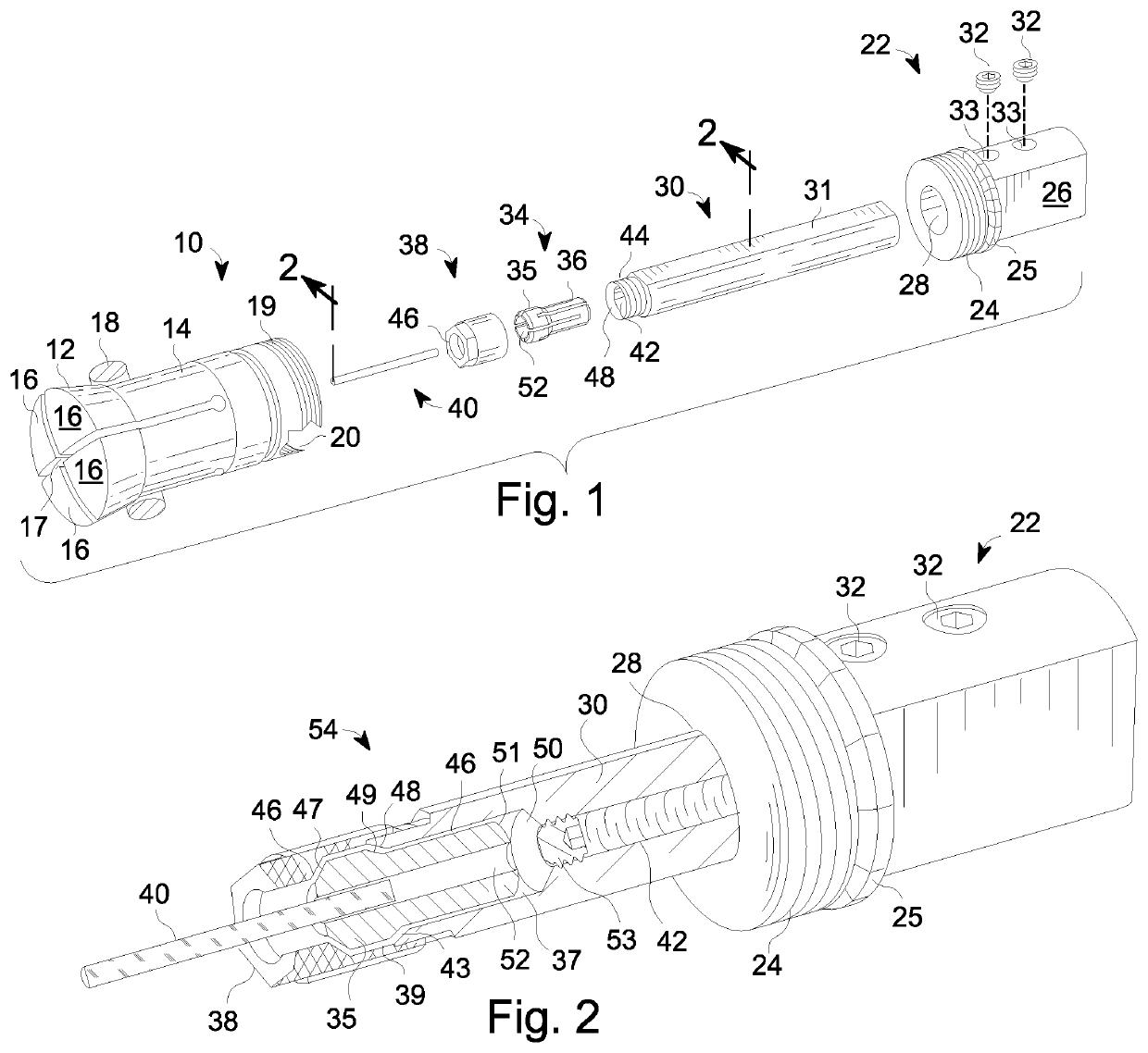
[0033]In the first embodiment best shown in FIGS. 1 and 2, elements of the work-holding-collet can be removed from the work-holding-collet 10 to be adjusted outside the work-holding-collet 10. The removable parts, together, can be referred to as a first removable component of the work-stop assembly. A main work-stop body 22 is a first part of the first removable component, is directly connected to the work-holding collet 10, and can be screwed or unscrewed from the work-holding-collet 10. The remaining parts of the first removable component are supported by the main work-stop body 22 in a passageway 28. These components are a shank 30 that is axially slidable in the axial passageway 28 through the main work-stop body 22; a stop nut that is threaded to the front of the shank, forming a stop-collet cavity between the nut and the front of the shank; and a stop-collet that can hold a work stop-rod 40 and fits in the cavity. The shank 30 is equipped with a hollow centerline bore behind t...

second embodiment

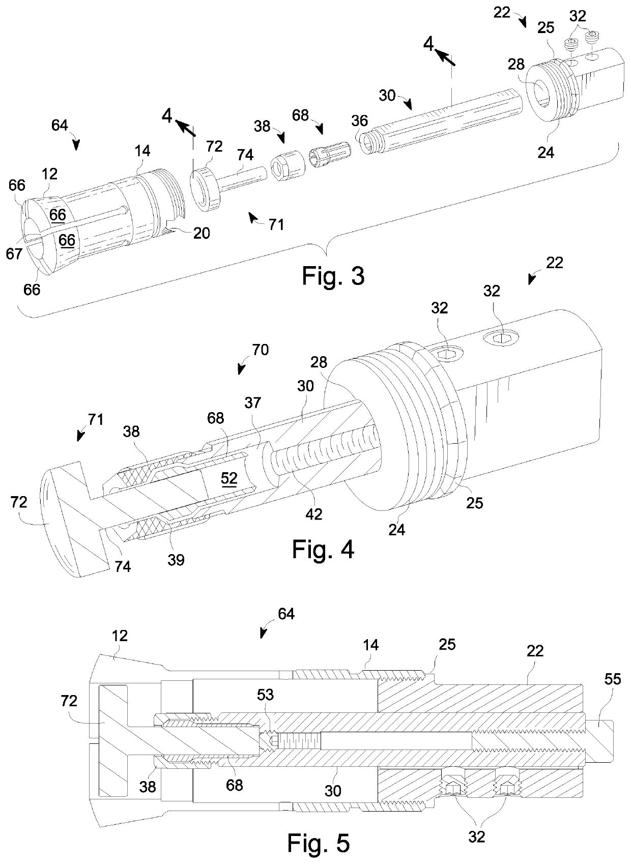
[0035]A second embodiment is best shown in FIGS. 3, 4, and 5 supports a tee-square stop-rod 71 with a broad head, beat suited for use with workpieces that are both radially wide and axially thin, such as washers. This type of stop-rod 71 can be troublesome unless it is held accurately. To achieve sufficiently accurate holding of stop-rod 71 in the passageway of the main work-stop body, the passageway is configured to have a one or more clamps to the slidable shank with equal lengths of the passageway both fore and aft of the one or more clamps.

third embodiment

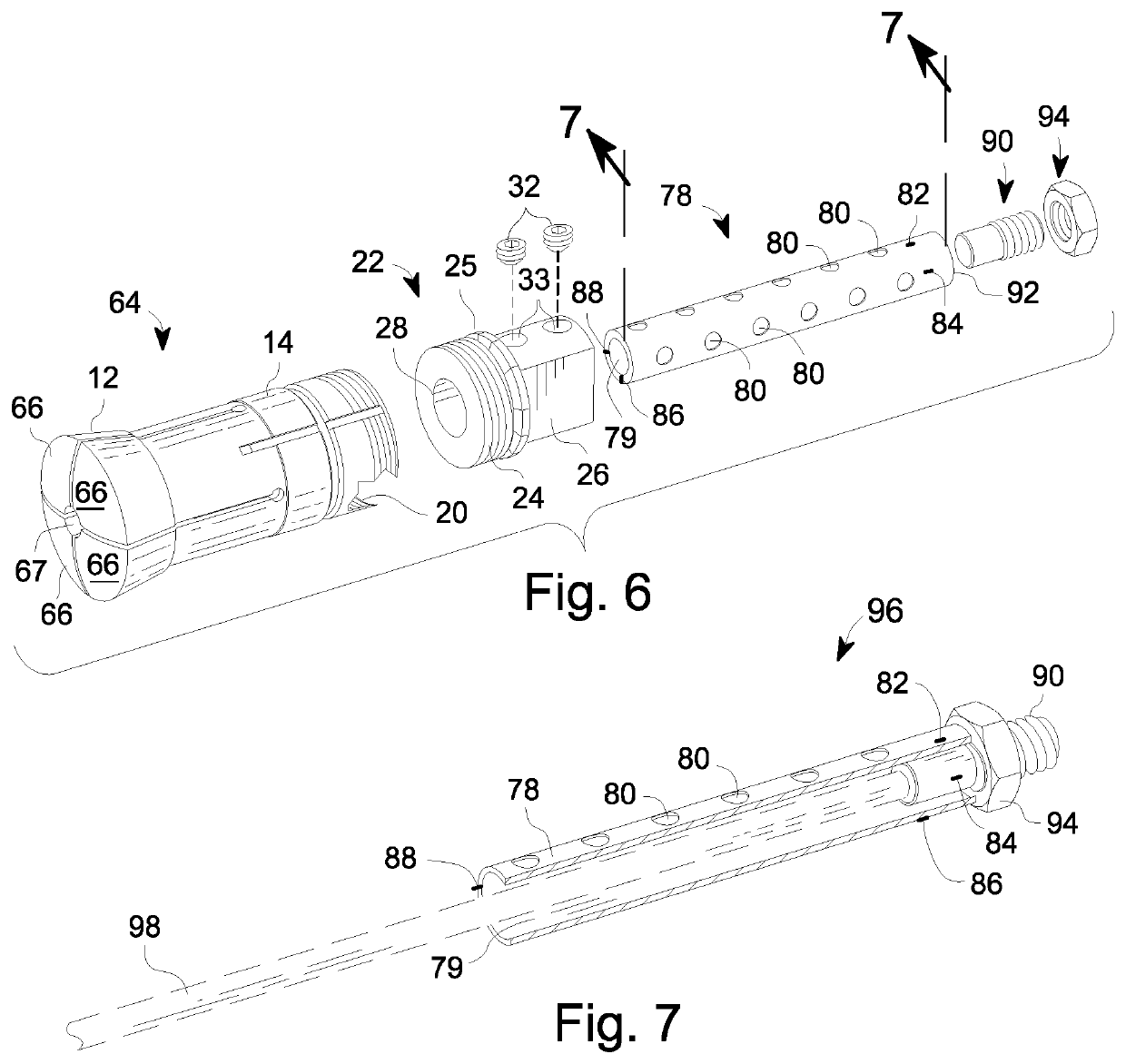
[0036]the stop assembly best shown in FIGS. 6 and 7 comprises a similar main work-stop body that is removably affixed to the rear of the work-holding-collet tube; a tube stop with open front and closed rear, that is slidable is an axial passageway of the work-stop body; an axially adjustable rod closing the rear of the tube stop; and a position securing fastener for fixing the position of the rod in the tube stop. As before, the fastening of the work-stop body enables repeatable precision engagement between the work-holding-collet and the work-stop body. Such repeatable precision engagement is by threaded engagement between the work-holding-collet and the work-stop body to a point of full available engagement. The work-stop body defines a passageway axially in line with the workpiece-receiving mouth of the work-holding-collet. A portion of the work-stop assembly that is slidable in the passageway can be rapidly and accurately locked in place in the passageway by one or more non-marr...


PUM


Abstract

A work-stop assembly in a work-holding-collet is formed of a main work-stop body selectively mounted on the rear of the work-holding-collet and defining a longitudinal through passageway aligned with the collet mouth. First and second work-stop position adjusters allow coarse adjustment of the position of a work-stop element by one of the adjusters while the work-stop assembly is removed from the work-holding collet and allow more precise adjustment by the other adjuster after the work-stop assembly is mounted to the work-holding collet. One of the adjustments employs a slidable relationship between the adjuster and the passageway, and one of the adjusters carries the work-stop element for axial movement in the work-holding-collet to set an adjustable depth limit for a workpiece inserted from a workpiece-receiving mouth at the front of the work-holding-collet.

Description

BACKGROUND OF THE INVENTIONField of the Invention[0001]The invention relates to chucks or turning and particularly to chucks with simultaneously acting jaws and longitudinally split sleeves, e.g. collet chucks, with a tool or workpiece positioning stop. The invention also relates to chucks, an accessory or component thereof, and a tool or work stop or locator.Description of Related Art[0002]including information disclosed under 37 CFR 1.97 and 1.98—Collet chucks provide a mechanical connection on machine tools to carry a tool or a workpiece in proper position for cutting or forming. A basic collet is an axially extending tube with a flared front end where the tube wall is split into several axial fingers or jaws. The interior of the tube extending rearward from the flared front can be referred to as a capacity bore, since within the capacity of the collet this area receives a portion of a workpiece. The workpiece can be placed in the capacity bore of the tube on the central axis of ...

Claims


Application Information

Patent Timeline
IPC IPC(8): B23B31/20
CPCB23B31/208B23B31/2012Y10T279/3487
Inventor KENNER, DANIEL R.
Owner KENNER DANIEL R
Why Eureka
Try Eureka