
Lens Module

Inactive Publication Date: 2021-04-15
AAC OPTICS SOLUTIONS PTE LTD
View PDF0 Cites 0 Cited by
  • Summary
  • Abstract
  • Description
  • Claims
  • Application Information

AI Technical Summary

Benefits of technology

The invention aims to create a lens module that can move smoothly and efficiently.

Problems solved by technology

This arrangement makes the structure of the lens module complicated, and the production efficiency reduces accordingly.

Method used


Image

  • Lens Module
  • Lens Module
  • Lens Module

Examples


Embodiment Construction

[0035]The present disclosure will hereinafter be described in detail with reference to several exemplary embodiments. To make the technical problems to be solved, technical solutions and beneficial effects of the present disclosure more apparent, the present disclosure is described in further detail together with the figure and the embodiments. It should be understood the specific embodiments described hereby are only to explain the disclosure, not intended to limit the disclosure.

[0036]The invention is further described below with reference to the drawings and embodiments.

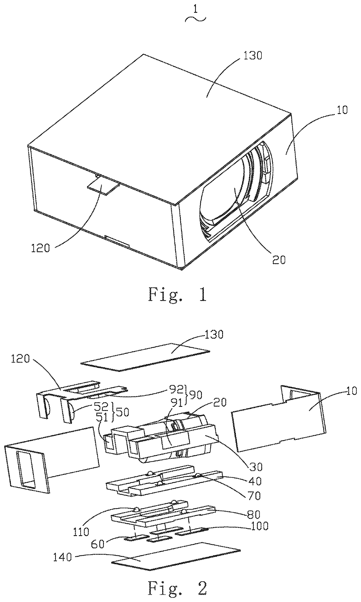
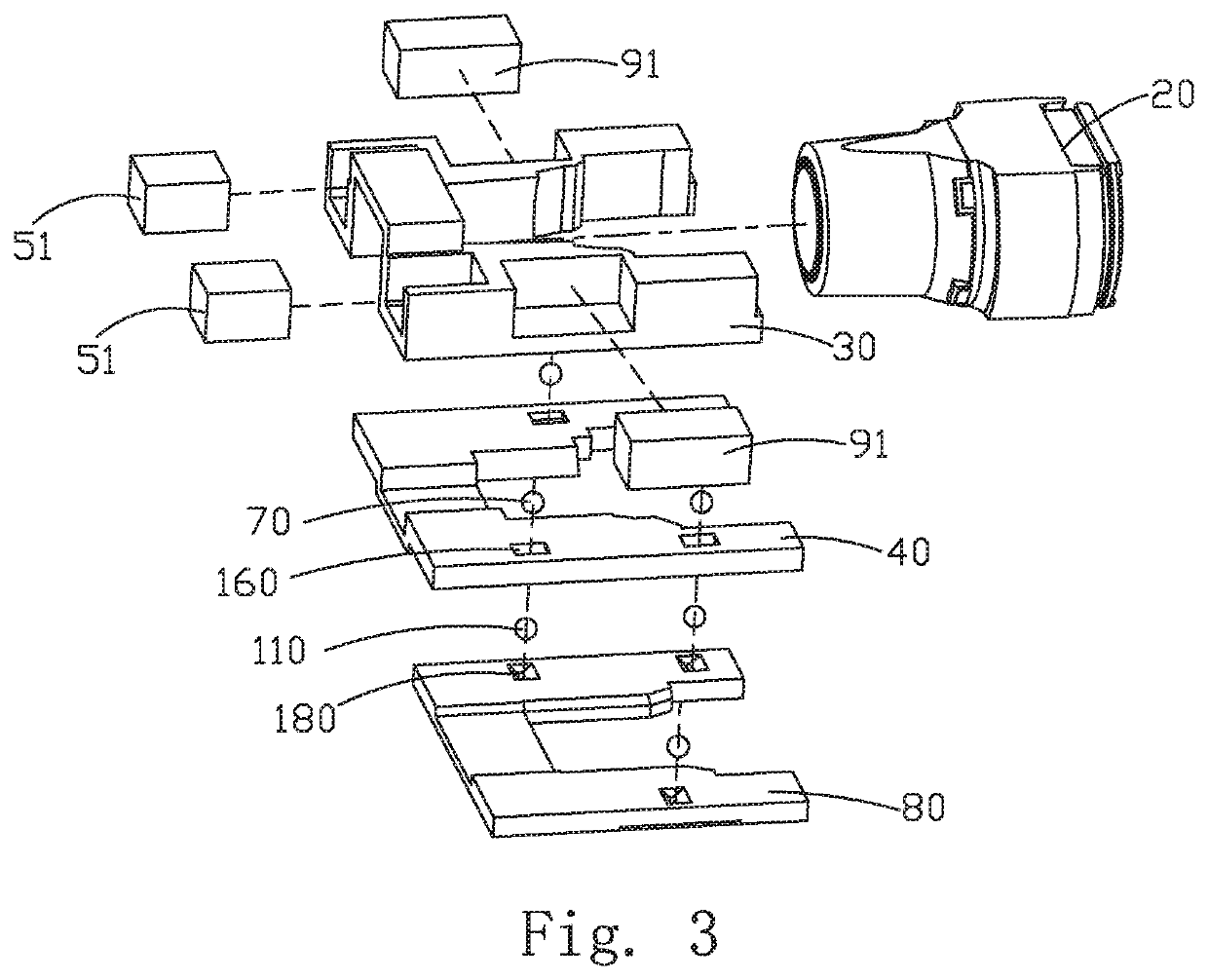
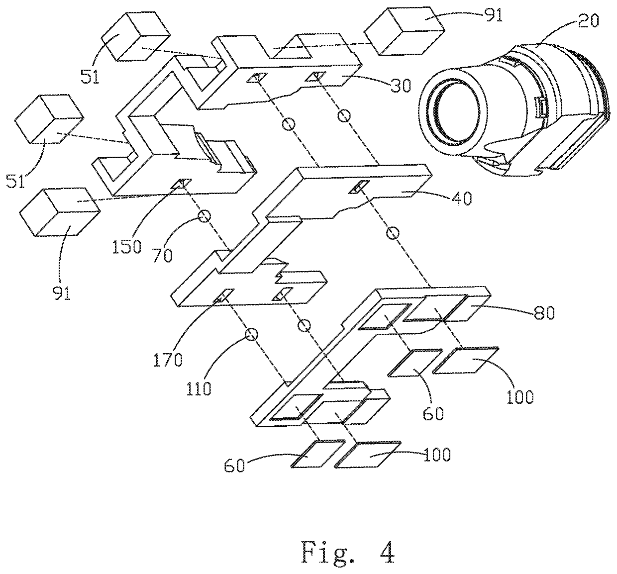
[0037]Referring to FIGS. 1-7, the first embodiment of the invention relates to a lens module 1, which comprises a housing body; a lens 20 accommodated in the housing body; an installation support frame 30 which fixes the lens 20; a first base 40 and a second base 80 arranged opposite to an installation support frame 30; a first driver piece 50 which causes the relative displacement of the lens 20 relative to the f...


PUM


Abstract

The invention provides a lens module having a housing body, a lens, an installation support frame that fixes the lens, a first base, a second base arranged opposite to the installation support frame, a first driver piece that drives the installation support frame to cause relative displacement of the lens relative to the first base, a second driver piece that drives the installation support frame to cause relative displacement of the lens relative to the second base in a direction perpendicular to the optical axis of the lens. The first base and the second base are fixed opposite in the housing body. In the invention, the lens is fixed through the installation support frame, the first driver piece is used to drive the relative displacement of the lens along its optical axis direction. As a result, the lens module has a simple structure and high production efficiency.

Description

FIELD OF THE PRESENT DISCLOSURE[0001]The invention relates to the field of optical imaging technology, and in particular to a lens module.DESCRIPTION OF RELATED ART[0002]In recent years, with the development of optical imaging technology and the rise of electronic products with imaging functions, optical lenses have been widely used in various electronic products. Generally, the light is irradiated directly from the object side, reaches the image side and by penetrating the lens component in a straight line along the optical axis. The lens component is used to image the object. The lens component generally has an auto focus function (auto focusing) and an optical image stabilization (OIS) function.[0003]The existing lens module utilizes an elastic suspension component to suspend the lens component in a fixation frame, and to cooperate with the magnet provided through the focusing coil to drive lens component to move along the optical axis direction to realize auto focusing of the le...

Claims


Application Information

Patent Timeline
IPC IPC(8): G02B27/64G02B7/09G03B5/00G03B13/36
CPCG02B27/646G02B7/09G03B13/36G03B5/00G02B7/08G02B7/02
Inventor LI, LINZHENLU, JILIANGLI, GANGZHANG, JINGU, CHUNXIN
Owner AAC OPTICS SOLUTIONS PTE LTD
Learn More