Force-feedback input device

Inactive Publication Date: 2005-05-12
ALPS ALPINE CO LTD
View PDF3 Cites 10 Cited by
  • Summary
  • Abstract
  • Description
  • Claims
  • Application Information

AI Technical Summary

Benefits of technology

[0017] Accordingly, it is an object of the present invention to provide a force-feedback input device generating an attractive force that allows a cursor to stably move even when a plurality of buttons is displayed on the display means.
[0019] As described above, when the first and second buttons are displayed on the display means, driving of the external-force generation portions is controlled such that the rate of decrease of the second external force becomes smaller than the rate of decrease of the first external force as the distance between the cursor and a borderline between a first attractive area and a second attractive area appearing in the vicinities of the adjacent first and second buttons becomes smaller. Consequently, even when the direction of the attractive force abruptly changes at a mid-position between the buttons, the change in strength of the second external force exerted on the operating portion can be moderate and, therefore, no unnatural click sensation occurs between the buttons and the cursor can be moved stably.
[0020] Preferably, in the force-feedback input device, the control means decreases only the first external force as the distance between the borderline and the cursor decreases.
[0021] As described above, since only the first external force is decreased as the distance between the borderline and the cursor decreases, a change in the strength of the second external force exerted on the operating portion can be eliminated. Therefore, no unnatural click sensation occurs between the buttons and the cursor can be moved stably.

Problems solved by technology

However, some of the known force-feedback input devices employ a joystick instead of a mouse.
However, the technology described in the publication discloses no method for controlling an attractive force when a plurality of buttons is displayed on display means, in particular, when the buttons are closely located to each other.
Therefore, when the technology described in that publication is applied to an actual device, and a cursor is moved from the display position of one button or the vicinity of the button to the display position of another button or the vicinity of the button, impact force occurs in the input means, and therefore, the operability of the input means becomes degraded or the cursor cannot be smoothly moved in the desired direction, which is a problem.
Accordingly, the strength of the attractive force abruptly changes and, thus, an unnatural click sensation occurs from button to button and causes an operator to feel an unpleasant sensation.
However, as can be seen from the comparison between FIG. 12B and FIG. 14B, this control method has a drawback that the cursor C cannot move stably on the line M2 parallel to the line M1 since the component force Fy of the attractive force in the y-axis direction significantly changes during the move.

Method used


Image

  • Force-feedback input device
  • Force-feedback input device
  • Force-feedback input device

Examples


Embodiment Construction

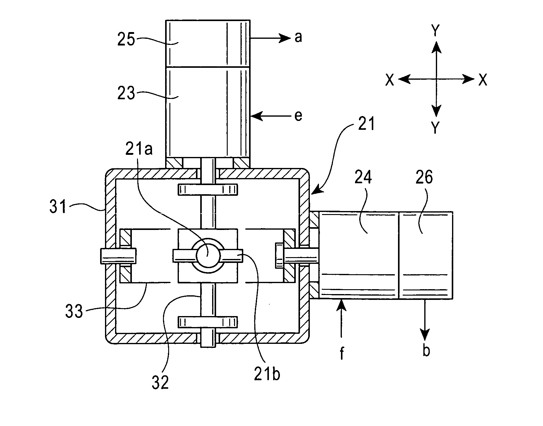
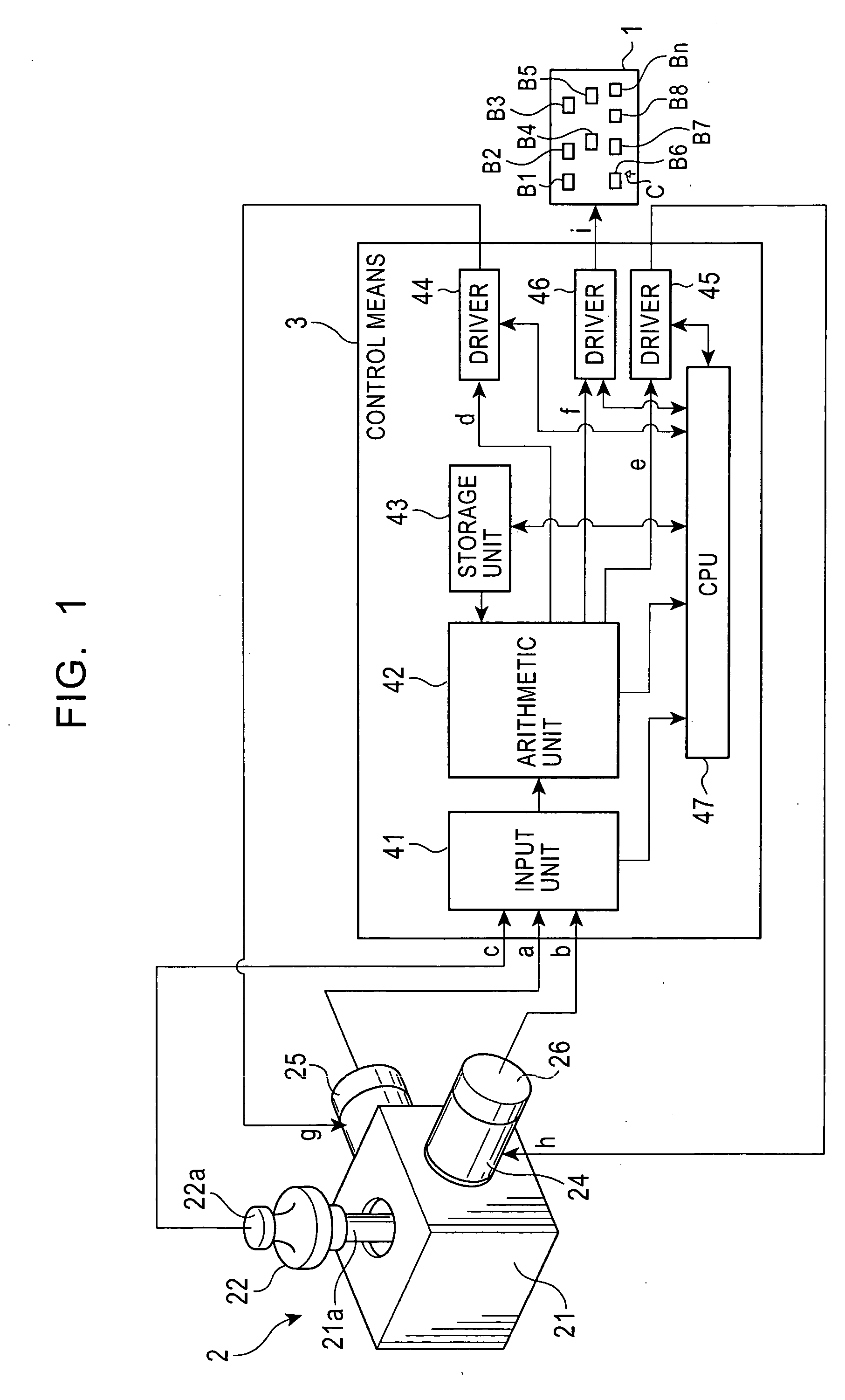
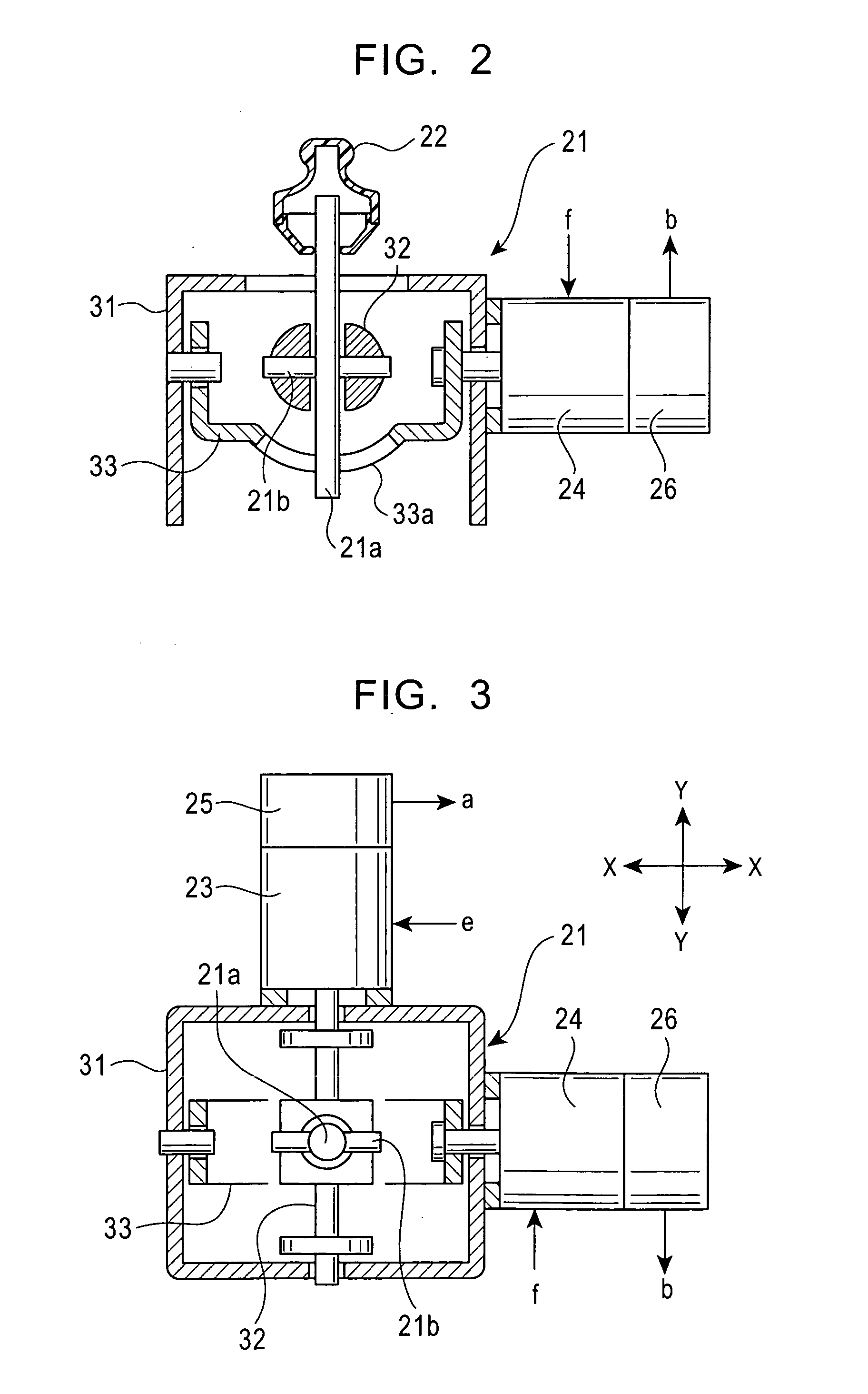
[0036] Embodiments of a force-feedback input device according to the present invention will be described below with reference to FIGS. 1 to 8. FIG. 1 is a block diagram of a force-feedback input device according to an embodiment of the present invention. FIG. 2 is a side cross-sectional view of input means according to an embodiment. FIG. 3 is a top plan cross-sectional view of the input means according to the embodiment. FIGS. 4A, 4B, and 4C are diagrams explaining the operation of the force-feedback input device according to the embodiment. FIG. 5 is a vector diagram illustrating a change in an attractive force exerted on the input means when two buttons are displayed on display means. FIG. 6 is a schematic diagram explaining a scheme for controlling the attractive force in the input means according to the embodiment. FIGS. 7A and 7B are graph charts illustrating the change in an attractive force exerted on the input means when two buttons are displayed on display means. FIG. 8 is...


PUM


Abstract

In a force-feedback input device, when a cursor moves on a line parallel to a line between a center of a first button and a center of a second button, two areas are determined on the line. One is an area between a first position, which corresponds to the center of the first button, and the mid-line between the first and second buttons. The other is an area between a second position, which corresponds to the center of the second button and the mid-line between the first and second buttons. In these areas, first and second external-force generation portions are controlled so that the direction of an attractive force exerted on an operating portion is biased towards a mid-point between the first and second buttons as the cursor moves closer to the mid-line between the two buttons.

Description

BACKGROUND OF THE INVENTION [0001] 1. Field of the Invention [0002] The present invention relates to a force-feedback input device used for, for example, car navigation systems and, in particular, to an improvement in the operational sensation of an input device having a function of automatically attracting a cursor into a position of a menu-selection button displayed on display means in order to facilitate the selection of a desired button. [0003] 2. Description of the Related Art [0004] Input devices are known in which display means displays menu-selection buttons and a cursor, and in which input means allows an operator to select a desired menu by moving the cursor to the display position of the desired button among the menu-selection buttons. In addition, some input means have a function that automatically attracts a cursor to the displayed position of the button to facilitate a movement of the cursor to the displayed button position. [0005]FIG. 9 is a block diagram of a known i...

Claims


Application Information

Patent Timeline
IPC IPC(8): G06F3/00G06F3/01G06F3/0338G06F3/038G06F3/0481G06F3/0487
CPCG06F2203/014G06F3/016
Inventor MATSUMOTO, KEN
Owner ALPS ALPINE CO LTD
Why Eureka
Try Eureka