
Alternating-current full magnetic power machine

a full magnetic power machine and alternating current technology, applied in the direction of generator/motor, magnetic circuit rotating parts, magnetic circuit shape/form/construction, etc., can solve the problems of constant introduction of new technical problems, low usage costs, and inability to reduce the electricity consumption of stators, so as to increase the driving torque of the rotor composite assembly, the usage range of alternating-current full magnetic power machines is also expanded, and the usage cost is low.

Inactive Publication Date: 2016-10-06
XIAN ZHANG
View PDF5 Cites 2 Cited by
  • Summary
  • Abstract
  • Description
  • Claims
  • Application Information

AI Technical Summary

Benefits of technology

The patent describes a motor that uses a stator composite magnetic head and a rotor with a permanent magnet to generate a strong magnetic field. This improves energy position, allowing for a smooth start without needing a high current. The motor also includes a protection ferrule and an air gap between the stator and the rotor to increase the driving torque. The motor can switch between different polarities to reduce magnetic resistance and change the strength of the field. Overall, this design provides a more efficient and consistent motor.

Problems solved by technology

Currently, the research on equipment that converts magnetic energy of a rare earth neodymium-iron-boron alloy super permanent magnet into mechanical energy is extremely urgent.
In a process of researching an entire system, a new technical problem is constantly put forward.
As a result, electricity consumption of the stator is not reduced, heat dissipation and energy consumption of the stator are extremely large, and an unsecure problem that a winding is burnt up because of overheating often occurs.
The machine can work stably for a long time in airless environment, is widely applied to various power devices, for example, being uses as a power source in special environment and a robot power source, and has excessively high social and economical values.

Method used


Image

  • Alternating-current full magnetic power machine
  • Alternating-current full magnetic power machine
  • Alternating-current full magnetic power machine

Examples


Embodiment Construction

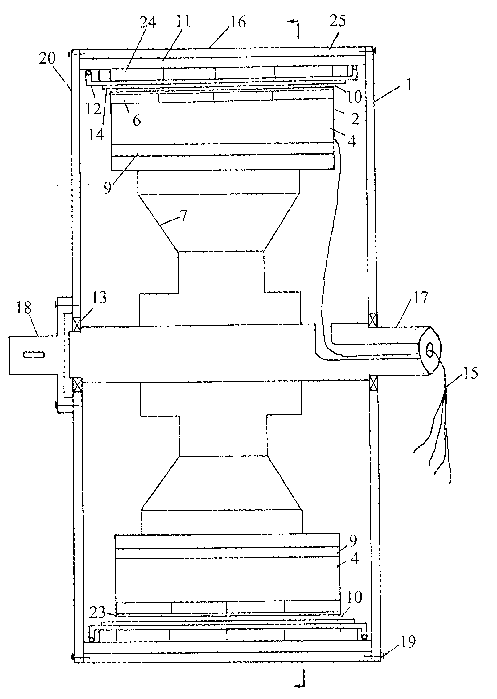
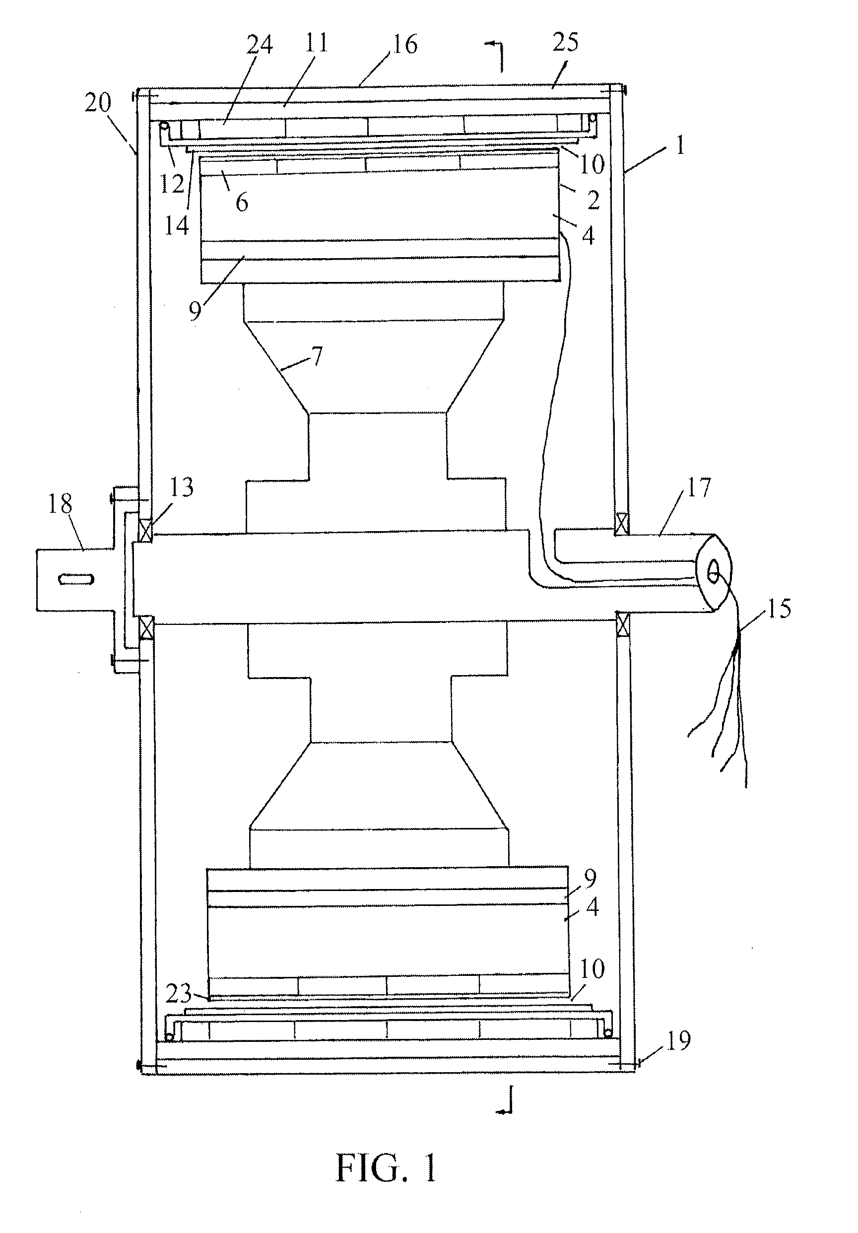
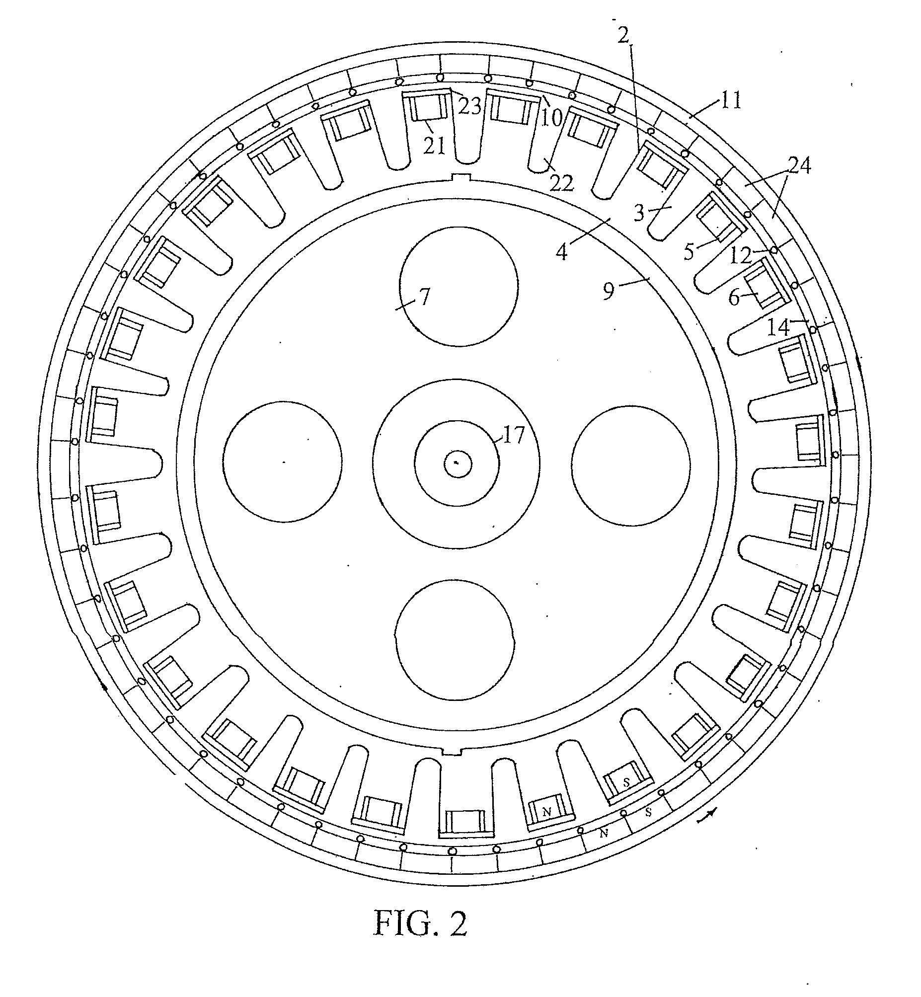
[0027]In embodiments of the present invention, referring to the foregoing FIG. 1, FIG. 2, FIG. 3, FIG. 4, FIG. 5, FIG. 6, and FIG. 7, an alternating-current full magnetic power machine 1 uses a three-phase alternating-current power supply. The alternating-current full magnetic power machine has a rotating housing inner stator type or a fixed housing rotary inner pivot type. In research of sample device design of the alternating-current full magnetic power machine 1, in an atlas of a commercially-available motor, a most commonly-used connecting rod diagram of single-layer crossing windings of slot 36 and pole 4 is selected. If a connecting rod diagram of windings above pole 4 is chosen, a rotating speed decreases, but the problem may be resolved by connecting a speed controller. As shown in FIG. 8, which is a schematic diagram of wire distribution and wire connection of the windings, an offset of the three-phase windings is 120 degrees. The rotating housing inner stator type includes...


PUM


Abstract

An alternating-current full magnetic power machine includes a stator and a rotor. The stator includes a stator iron core and multiple coil windings that are built in a cable trough of the stator iron core in sequence, a pole of the stator iron core is provided with a groove, a stator the permanent magnet is disposed in the groove, a metal-plate of a fence-like mesh structure is fixed on a pole surface, and multiple stator composite magnetic heads made of the stator the permanent magnet and the metal-plate are disposed in the coil windings, the pole, and the groove. The rotor includes a rotor iron hoop made of a compound material, a non-magnetic material surface of the rotor iron hoop is provided with multiple rotor permanent magnets, and a metallic copper or an aluminous squirrel cage closed frame is disposed on a rotor permanent magnet surface.

Description

BACKGROUND[0001]1. Technical Field[0002]The present invention relates to a permanent magnetic electrical machine that converts magnetic energy into mechanical energy and relates to the field of rare earth permanent magnet the magnetic energy conversion technologies, and in particular, to an alternating-current full magnetic power machine.[0003]2. Related Art[0004]Currently, the research on equipment that converts magnetic energy of a rare earth neodymium-iron-boron alloy super permanent magnet into mechanical energy is extremely urgent. In a process of researching an entire system, a new technical problem is constantly put forward. Although energy saving of a rotor of a permanent magnetic motor is obvious by means of a rare earth permanent magnet, an excitation coil is still used on a stator. As a result, electricity consumption of the stator is not reduced, heat dissipation and energy consumption of the stator are extremely large, and an unsecure problem that a winding is burnt up ...

Claims


Application Information

Patent Timeline
IPC IPC(8): H02K1/17H02K3/46H02K5/16H02K1/27
CPCH02K1/17H02K5/161H02K3/46H02K1/27H02N11/008H02K21/00H02K21/44
Inventor ZHANG, XIANZHANG, WENJIEZHU, XIAOYAN
Owner XIAN ZHANG
Learn More