Axial flux machine

a technology of flux machine and axial shaft, which is applied in the direction of cooling/ventilation arrangement, magnetic circuit rotating parts, shape/form/construction, etc., can solve the problems of rotor and magnet heat up, significant amount of heat, and provide adequate cooling, so as to achieve efficient air cooling and work harder for longer

Active Publication Date: 2020-04-21
YASA LIMITED
View PDF13 Cites 2 Cited by
  • Summary
  • Abstract
  • Description
  • Claims
  • Application Information

AI Technical Summary

Benefits of technology

[0008]By using the impellor blades and impellor cover, an efficient air cooling mechanism may be provided to the rotor of the machine, which enables the rotor to work harder for longer: heat generated by eddy-currents in the magnets and back-iron is transferred to the air meaning the rotor runs cooler for a given speed / torque requirement.

Problems solved by technology

One difficulty with electric machines generally is to provide adequate cooling.
This is a particular problem with a Y machine having a high torque density because significant heat is generated in the coils at high torques and is often a limiting factor in the torques that can be employed, at least for extended periods of time.
However, with axial flux machines, eddy currents in the magnets and rotor structure (housing the magnets) may cause the rotor and the magnets to heat up.
Whilst cooling the stator also cools the rotor to some extent (through heat being transferred by a hub or bearing assembly, for example, between the rotor and stator), there still may remain a significant amount of heat in the rotors, which will adversely affect the performance of the machine, since the properties of the magnets deteriorate as their temperature increases.
However, often these solutions impact on the design of the machine, for example, by increasing the axial length of the machine, which is not desirable.
Furthermore, due to tolerances in the design and manufacture of the machines, the cooling performance of such fans and structures varies from machine to machine, which is undesirable.
Such a configuration is not feasible with an axial flux motor.

Method used


Image

  • Axial flux machine
  • Axial flux machine
  • Axial flux machine

Examples


Embodiment Construction

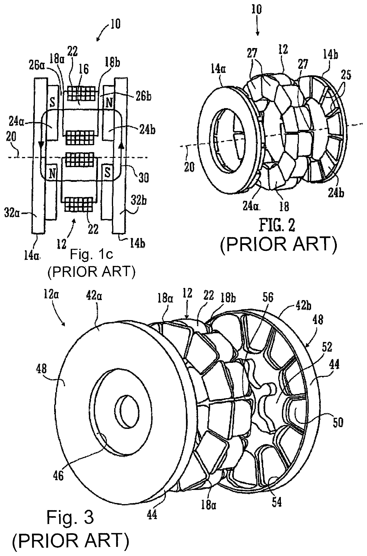
[0040]Referring first to FIGS. 1c, 2 and 3, which are taken from our PCT application WO2012 / 022974, FIG. 1c shows a schematic illustration of a yokeless and segmented armature machine 10.

[0041]The machine 10 comprises a stator 12 and two rotors 14a,b. The stator 12 is a collection of separate stator bars 16 spaced circumferentially about a rotation axis 20 of the rotors 14a,b. Each bar 16 has its own axis (not shown) which is preferably, but not essentially, disposed parallel to the rotation axis 20. Each end of each stator bar is provided with a shoe 18a,b which serves a physical purpose of confining a coil stack 22, which stack 22 is preferably of square / rectangular section insulated wire so that a high fill factor can be achieved. The coils 22 are connected to an electrical circuit (not shown) that, in the case of a motor, energizes the coils so that the poles of the resultant magnetic fields generated by the current flowing in the coils is opposite in adjacent stator coils 22.

[0...


PUM


Abstract

An axial flux machine (100) is provided, in which the rotor (104) is cooled via air cooling, provided by impeller blades (140) located on the opposite side of the rotor (104) to the stator (102). An impeller cover (142) covers the impeller blades (140) such that air channels are defined between adjacent blades. The air channels have an air inlet (146) at an inner radial portion of the rotor (104), and an air outlet (146) at the outer radial extremity of the impeller blades (140). As the rotor (104) turns, the air is drawn through the air channel from the air inlet (144) to the air outlet (146). The motor (100) may be enclosed within a housing (120), in which case air ducting (150,152) may be used to guide air to the air inlet (144), and from the air outlet (146) to the outside of the housing (120).

Description

FIELD OF THE INVENTION[0001]The present invention relates to axial flux machines.BACKGROUND OF THE INVENTION[0002]In the present invention, we are concerned with axial flux permanent magnet machines. Broadly speaking these have disc- or ring-shaped rotor and stator structures arranged about an axis. Typically the stator comprises a set of coils each parallel to the axis and the rotor bears a set of permanent magnets and is mounted on a bearing so that it can rotate about the axis driven by fields from the stator coils. FIG. 1a shows the general configuration of an axial flux machine of the present invention with a pair of rotors R1, R2 to either side of a stator S—although a simple structure of the present invention could omit one of the rotors. As can be seen there is an air gap G between a rotor and a stator and in an axial flux machine the direction of flux through the air gap is substantially axial.[0003]There are various configurations of axial flux permanent magnet machine dep...

Claims


Application Information

Patent Timeline
Patent Type & Authority Patents(United States)
IPC IPC(8): H02K9/06H02K5/20H02K21/24H02K9/18
CPCH02K5/20H02K21/24H02K9/06H02K2213/12H02K9/18H02K5/207H02K1/32
Inventor MCCAW, CHRISTOPHER THOMAS
Owner YASA LIMITED
Why Eureka
Try Eureka