Infrared touch display device and method of fabricating same

a display device and infrared technology, applied in the field of display technologies, can solve the problems of poor poor experience, and a sense of separation, and achieve the effects of enhancing user experience, enhancing waterproof and dustproof effects of display devices, and reducing the sense of separation

Active Publication Date: 2021-04-29
SHENZHEN CHINA STAR OPTOELECTRONICS SEMICON DISPLAY TECH CO LTD
View PDF0 Cites 0 Cited by
  • Summary
  • Abstract
  • Description
  • Claims
  • Application Information

AI Technical Summary

Benefits of technology

[0036]Beneficial effects of the present disclosure are that: the infrared touch display device and the method of fabricating the same employ an air-bonding method to bond the cover plate with the display panel in a vacuum environment, and a portion of the cover plate corresponding to a central portion surrounded by the sealant is pressed toward the display panel in the vacuum environment, such that the cover plate is recessed toward the display panel and closely attached to the display panel, thereby eliminating the sense of separation between the cover plate and the display panel, enhancing user's experience. In addition, such a method can make the cover plate and the display panel fully bonded, and enhance the waterproof and dustproof effects of the display device in the sealant. Furthermore, the infrared touch component is disposed in the non-recessed area of the cover plate, and the central portion of the cover plate is recessed, so as to avoid the problem that the cover plate may protrude to block the signal transmission when the infrared touch component is prepared on the surface of the cover plate.

Problems solved by technology

However, the air-bonding technology solely relies on a sealant for the sealing, and a cavity is formed between a central portion of the cover plate and a central portion of the display panel, causing problems of poor waterproof and dustproof effects and a sense of separation, resulting in a bad experience.
In addition, when the infrared touch is close to a surface of the cover plate, due to poor stability of the cavity, the cover plate may protrude to block the signal transmission.
Therefore, there is an urgent need to improve drawbacks of the prior art.

Method used


Image

  • Infrared touch display device and method of fabricating same
  • Infrared touch display device and method of fabricating same
  • Infrared touch display device and method of fabricating same

Examples


Embodiment Construction

[0044]The following description of the various embodiments is provided to illustrate the specific embodiments of the invention. Directional terms mentioned in the present invention, such as “vertical”, “horizontal”, “upper”, “bottom”, “pre”, “post”, “left”, “right”, “inside”, “outside”, “side”, etc., only refer to the direction of the additional drawing. Therefore, the directional terminology used is for the purpose of illustration and understanding of the invention. In the figures, structurally similar elements are denoted by the same reference numerals.

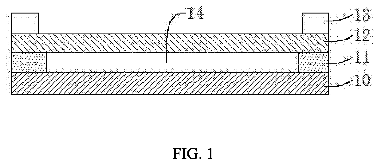
[0045]First, the prior art will be briefly described. Referring to FIG. 1, FIG. 1 is a schematic structural diagram of an infrared touch display device in the prior art. The infrared touch display device includes a display panel 10, a cover plate 12 disposed above the display panel 10, a colloid 11 disposed between the display panel 10 and the cover plate 12, and an infrared touch component 13 disposed on a periphery of the cover pl...


PUM

PropertyMeasurementUnit
pressureaaaaaaaaaa
thicknessaaaaaaaaaa
stabilityaaaaaaaaaa

Abstract

The present application provides an infrared touch display device and a fabrication method thereof. In the present application, a cover plate coated with a sealant and a display panel are sent into a vacuum chamber and vacuumed; when the cover plate is attached to the display panel, the cover plate corresponds to The portion of the central portion enclosed by the frame rubber is recessed toward the display panel side and closely fits with the display panel, and the periphery of the display panel and the periphery of the cover plate are sealed by the sealant; Group infrared emitting tubes and infrared receiving tube.

Description

BACKGROUND OF INVENTIONField of Invention[0001]The present application relates to a field of display technologies, and in particular, to an infrared touch display device and a method of fabricating the same.Description of Prior Art[0002]In a display field, infrared touch currently dominates a large part of the market due to mature technology, accurate touch accuracy, and cost-effective advantage. The infrared touch is to analyze a touch position through positioning by blocking the infrared light emitted by an infrared frame. A display panel and a glass cover plate are generally combined primarily by a direct-bonding or air-bonding. The touch display device that is attached by the air-bonding technology has lower cost than the touch display device that is attached by the direct-bonding technology. However, the air-bonding technology solely relies on a sealant for the sealing, and a cavity is formed between a central portion of the cover plate and a central portion of the display pane...

Claims


Application Information

Patent Timeline
Patent Type & Authority Applications(United States)
IPC IPC(8): G06F3/041G06F3/042
CPCG06F3/0412G06F2203/04103G06F3/0421
Inventor HU, CHONGMINGHSIAO, YUCHUNTANG, GUOFUZHOU, MINGJUN
Owner SHENZHEN CHINA STAR OPTOELECTRONICS SEMICON DISPLAY TECH CO LTD
Why Eureka
Try Eureka