Display device for a vehicle having migration of image display

a technology of image display and display device, which is applied in the direction of static indicating device, instruments, transportation and packaging, etc., can solve the problem of difficult to notice front headlights, and achieve the effect of facilitating understanding

Active Publication Date: 2021-04-29
TOYOTA JIDOSHA KK
View PDF0 Cites 0 Cited by
  • Summary
  • Abstract
  • Description
  • Claims
  • Application Information

AI Technical Summary

Benefits of technology

The display device described in this patent allows passengers to receive notifications about changes in the function of the vehicle without being affected by the notification process. This is accomplished through a display that is easy for passengers to understand. Overall, the device improves the user experience and helps passengers quickly and easily understand the functions of the vehicle.

Problems solved by technology

For example, it is difficult to notice when front headlights have been switched on at dusk through a window.
However, the display device of the first aspect is capable of emphatic visual communication to the occupant of an operational state that is difficult for the occupant to notice, such as an illuminated state of automatic lighting.

Method used


Image

  • Display device for a vehicle having migration of image display
  • Display device for a vehicle having migration of image display
  • Display device for a vehicle having migration of image display

Examples


first exemplary embodiment

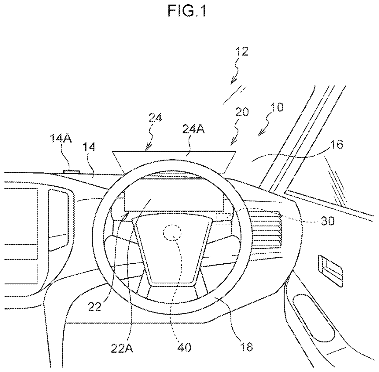
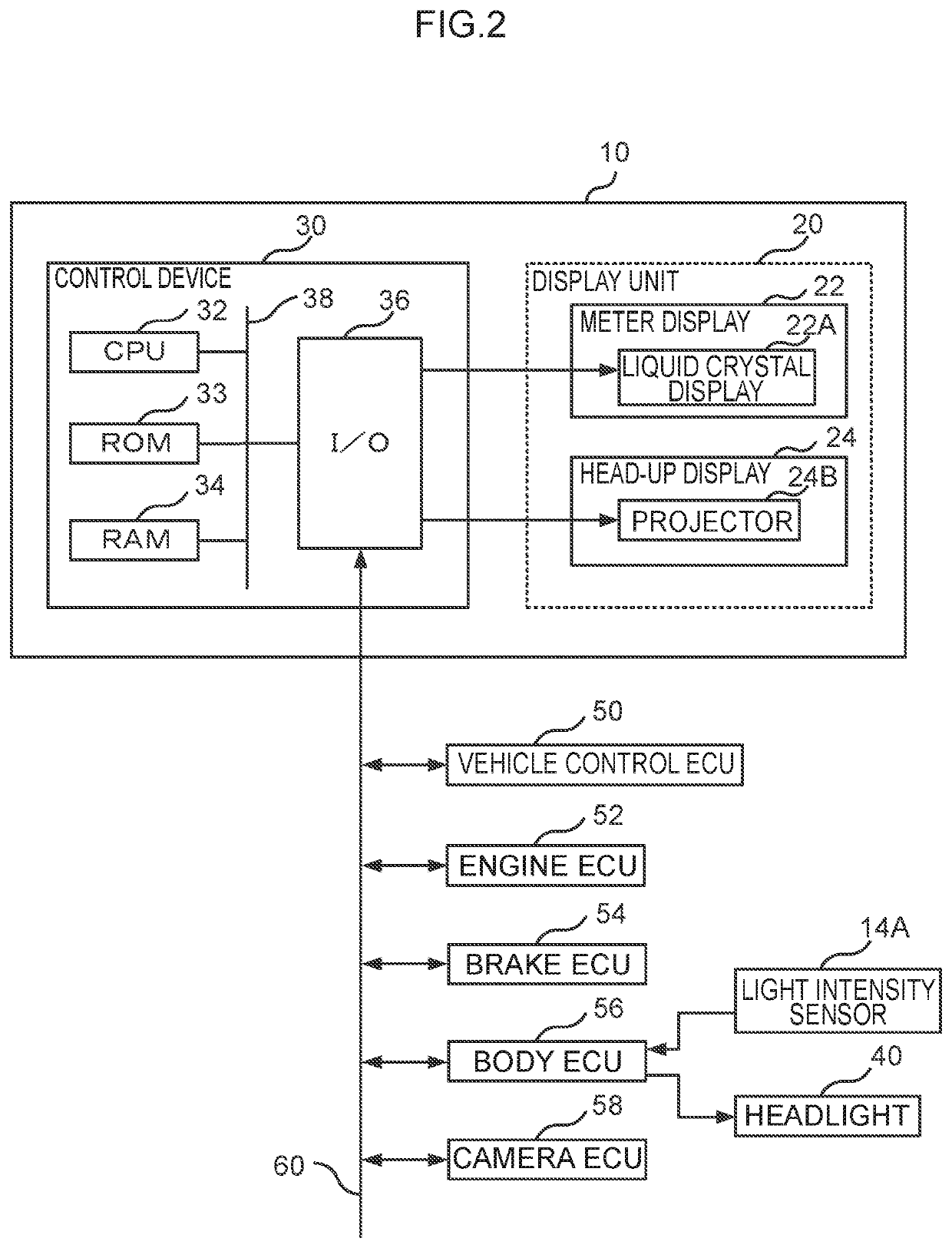
[0033]FIG. 1 illustrates a display device 10 of a first exemplary embodiment. As illustrated in FIG. 1, the display device 10 of the present exemplary embodiment includes a display unit 20 provided in front of an occupant in a driving seat of a vehicle 12, and a control device 30 that controls image contents displayed on the display unit 20.

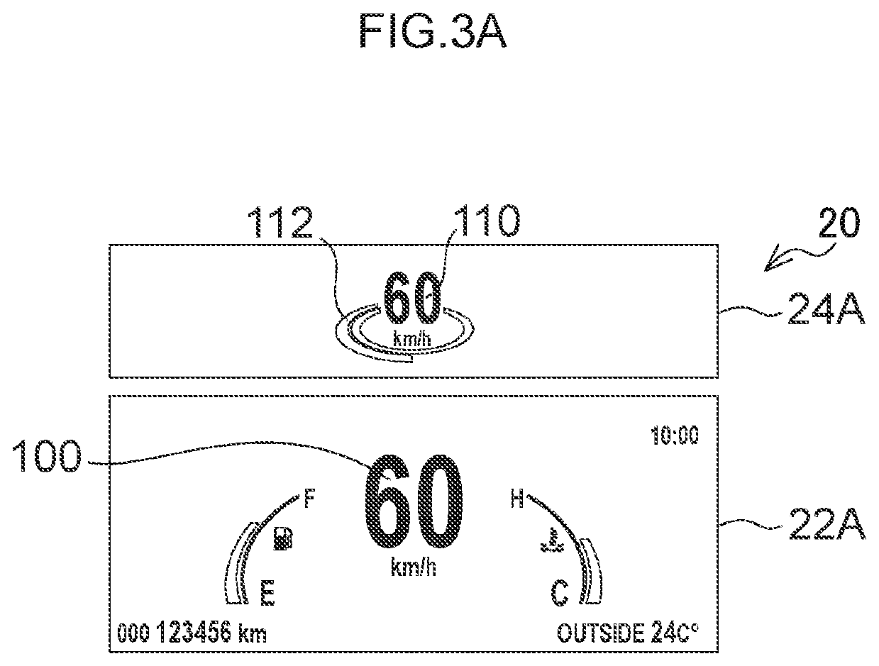
[0034]The display unit 20 includes a liquid crystal display 22A serving as a first display unit provided at a meter display 22, and a projection screen 24A serving as a second display unit provided at a projection screen of a head-up display 24. The projection screen 24A displays an image adjacent to and at the vehicle upper side of the liquid crystal display 22A, in a line of sight of the occupant.

[0035]To explain further, in the vehicle 12 of the present exemplary embodiment, the meter display 22 is provided in front of a dashboard 14. The liquid crystal display 22A is provided in front of the meter display 22. In the vehicle 12 of the present ...

second exemplary embodiment

[0053]A second exemplary embodiment is an example of the display unit 20 in a case in which a VSC function has been disabled by an occupant.

[0054]Although safety devices such as VSC are normally activated when the vehicle 12 is started up, these functions can be disabled using a switch provided on a center console or the like. For example, as illustrated in FIG. 4A, in cases in which the occupant has disabled the VSC function, a function-disabled indicator 140 indicating that the VSC function has been disabled is displayed on the left side of the liquid crystal display 22A.

[0055]At this time, the vehicle speed image 100 indicating the speed of the vehicle 12 is displayed at the center of the liquid crystal display 22A, the vehicle speed image 110 indicating the speed of the vehicle 12 is displayed at the center of the projection screen 24A, and the level image 112 indicating a vehicle speed level is displayed around the vehicle speed image 110.

[0056]After a preset duration has elaps...


PUM


Abstract

There is provided a display device for a vehicle, the display device including: a first display unit that is provided at a meter display and that is visible to an occupant of a vehicle; a second display unit that is provided at a projection surface of a head-up display, and that is above and adjacent to the first display unit in a line of sight of the occupant; a memory; and a processor that is connected to the memory, in a case in which an operational state of a function relating to the vehicle has automatically changed, the processor causing display of an image indicating the operational state on the second display unit, and then causing migration of display of the image to the first display unit.

Description

CROSS-REFERENCE TO RELATED APPLICATION[0001]This application is a divisional of U.S. application Ser. No. 16 / 502,155 filed Jul. 3, 2019, which is based on and claims priority under 35 USC 119 from Japanese Patent Application No. 2018-140603 filed on Jul. 26, 2018, the entire disclosure of these prior applications being incorporated by reference herein.BACKGROUNDTechnical Field[0002]The present disclosure relates to a display device for a vehicle.Related Art[0003]Japanese Patent Application Laid-Open (JP-A) No. 2011-230625 discloses a display device for a vehicle including a meter serving as a first display section, and a head-up display serving as a second display section.[0004]This display device for a vehicle has a function to coordinate the brightness of the meter display and the brightness of the display on the head-up display with each other.[0005]However, in display devices for a vehicle including a meter and a head-up display, it is desirable that the contents of a display on...

Claims


Application Information

Patent Timeline
Patent Type & Authority Applications(United States)
IPC IPC(8): G06F3/14G02B27/01B60K37/02
CPCG06F3/1446G09G5/10B60K37/02G02B27/0101B60K35/00B60R16/02G09G2320/0626G09G2380/10G09G5/12G02B2027/0118G02B27/01G02B2027/0141G02B2027/0183G06F3/1423B60K35/22B60K2360/1523B60K35/23B60K35/29B60K2360/182B60K2360/1868G09G2360/144B60K35/60
Inventor HIROTA, TAKAHIROAIKAWA, KOJIMURAMATU, SHIGETO
Owner TOYOTA JIDOSHA KK
Why Eureka
Try Eureka