Vehicle display device

a display device and vehicle technology, applied in vehicle components, instruments, projectors, etc., can solve the problems of overheating of the display device, difficulty in precisely grasping the application of external light to the display device, and inability to reduce the temperature of the display device at an appropriate time, so as to prevent optical deterioration of the display device and prevent the breakage of the display device

Active Publication Date: 2021-05-06
YAZAKI CORP
View PDF0 Cites 1 Cited by
  • Summary
  • Abstract
  • Description
  • Claims
  • Application Information

AI Technical Summary

Benefits of technology

[0006]The present invention has been made in view of the above problem, and an object thereof is to provide a vehicle display device that prevents optical deterioration of a display device caused by external light and prevents breakage of the display device caused by external light.

Problems solved by technology

For example, when external light, such as sunlight, enters the housing through the opening and reaches the display device through, for example, the reflecting mirror, a light collecting action of the reflecting mirror may cause overheating of the display device.
However, the temperature rise in the display device cannot be reduced at an appropriate timing because the dimming or the like of lighting of the display device is performed after the temperature of the display device exceeds the threshold temperature.
The method that detects external light using the infrared sensor disposed on the back face of the reflecting mirror does not detect external light actually applied to the display device.
Thus, it is difficult to precisely grasp the application of external light to the display device, and the method is thus susceptible to improvement in this point.

Method used


Image

  • Vehicle display device
  • Vehicle display device
  • Vehicle display device

Examples


first embodiment

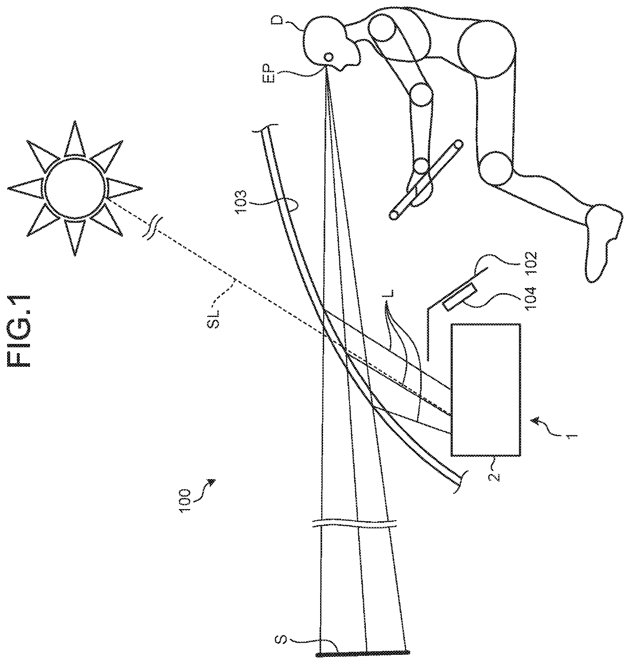
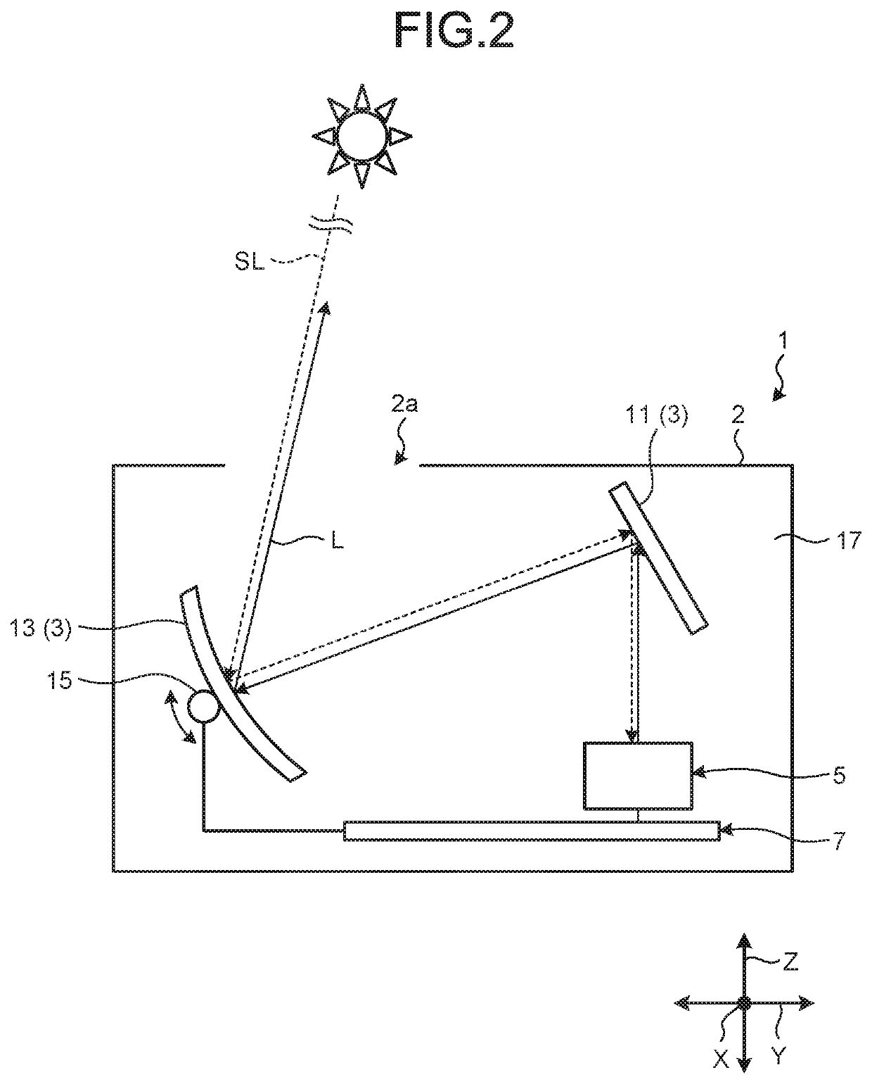
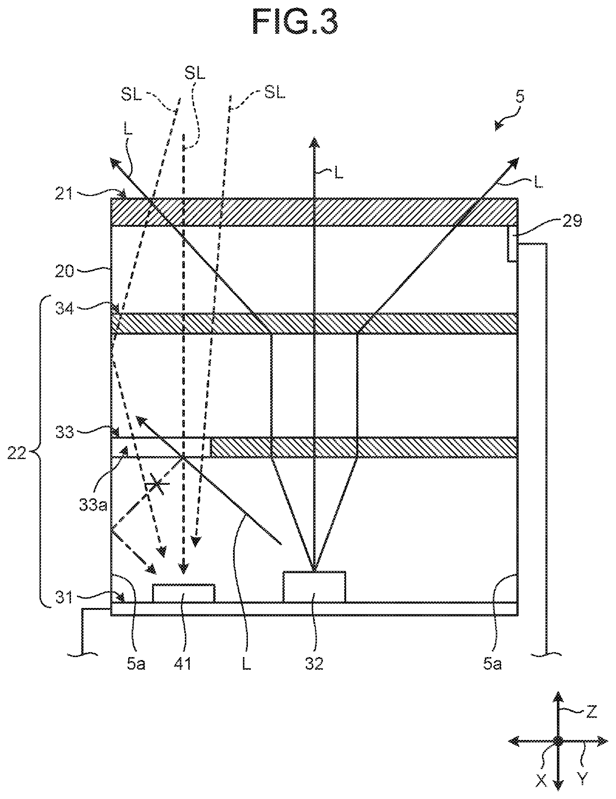
[0026]A vehicle display device according to the present invention will be described with reference FIGS. 1 to 6A and 6B. FIG. 1 is a schematic diagram illustrating an example of the vehicle display device according to the first embodiment when the vehicle display device is mounted on a vehicle. FIG. 2 is a schematic diagram illustrating the schematic configuration of the vehicle display device according to the first embodiment. FIG. 3 is a schematic diagram illustrating the schematic configuration of a display device according to the first embodiment. FIG. 4 is a schematic diagram illustrating the schematic configuration of a first optical member according to the first embodiment. FIG. 5 is a flowchart illustrating an example of a control operation of a controller according to the first embodiment. FIG. 6A is a graph illustrating the relationship between a detection value of a temperature sensor and a threshold, and FIG. 6B is a table illustrating the relationship between detection ...

second embodiment

[0050]Next, a vehicle display device according to a second embodiment will be described with reference to FIG. 7. FIG. 7 is a schematic diagram illustrating the schematic configuration of a display device according to the second embodiment.

[0051]A vehicle display device 1 according to the second embodiment differs from the vehicle display device 1 according to the first embodiment in that a display device 5 is provided with a light-shielding wall 44 inside thereof. In the following description, elements common between the first and second embodiments are designated by the same reference signs, and detailed description thereof will be omitted or simplified.

[0052]The light-shielding wall 44 is disposed between the light source 32 and the optical sensor 41 and blocks light traveling from the light source 32 to the optical sensor 41. For example, the light-shielding wall 44 is made of an opaque synthetic resin material that does not transmit light applied thereto from the light source 3...


PUM

PropertyMeasurementUnit
opticalaaaaaaaaaa
temperatureaaaaaaaaaa
optical pathaaaaaaaaaa

Abstract

A vehicle display device includes a display device, a reflecting mirror, an optical sensor configured to detect external light, and a controller configured to enable execution of a temperature lowering operation. The display device includes a light transmissive liquid crystal display unit disposed on an optical path of light emitted from a light source and a first optical member disposed between the liquid crystal display unit and the light source and configured to change an optical path of light that enters the first optical member from the light source and passes therethrough toward the liquid crystal display unit. The optical sensor is disposed on an optical path of the external light incident on the display device at a side opposite to the liquid crystal display unit across the first optical member. The first optical member includes a passage on an optical path through which the external light passes.

Description

CROSS-REFERENCE TO RELATED APPLICATION(S)[0001]The present application claims priority to and incorporates by reference the entire contents of Japanese Patent Application No. 2019-198846 filed in Japan on Oct. 31, 2019.BACKGROUND OF THE INVENTION1. Field of the Invention[0002]The present invention relates to a vehicle display device.2. Description of the Related Art[0003]Some known vehicles, such as motor vehicles, are equipped with a head-up display (HUD) device. The HUD device projects a display image displayed on a display device onto a windshield or a combiner through, for example, a reflecting mirror so that a driver visually recognizes the display image as a virtual image. When a display image displayed on the display device inside a housing is projected onto, for example, a windshield outside the housing, the HUD device is provided with an opening on the upper part of the housing. For example, when external light, such as sunlight, enters the housing through the opening and r...

Claims


Application Information

Patent Timeline
Patent Type & Authority Applications(United States)
IPC IPC(8): B60K35/00G02B27/01G02F1/1335
CPCB60K35/00G02B27/0101G02F1/133553B60K2370/1529B60K2370/334B60K2370/48G02F1/133512G03B21/28G02F1/1336H05K7/20954B60K2370/23B60K2370/52B60K2370/785B60K2370/25G02B27/0006
Inventor MIYAKE, YUTAYAGIMURATA, NAOHISASUGIURA, YUSUKE
Owner YAZAKI CORP
Why Eureka
Try Eureka