
Liquid treatment method and apparatus

a liquid treatment and liquid technology, applied in the direction of water treatment parameter control, specific water treatment objectives, chemical/physical/physico-chemical processes, etc., can solve the problems of reducing the overall efficiency, and adding to the cost of constructing and maintaining prior art systems

Active Publication Date: 2021-06-03
NOVOLABS LTD
View PDF0 Cites 0 Cited by
  • Summary
  • Abstract
  • Description
  • Claims
  • Application Information

AI Technical Summary

Benefits of technology

The patent text explains that the documents described in it have not been determined to be prior art and can be combined with other documents. The technical effect of this is that the documents can be used without permission or limitation, and can be combined with other materials to create new products or services.

Problems solved by technology

Any system where the ultraviolet radiation source is submerged in the liquid has electrical connection and associated waterproofing complexities.
These systems also typically require a quartz barrier to protect the ultraviolet light source from the liquid, with the barrier absorbing some of the ultraviolet radiation and reducing the overall efficiency.
These complexities add to the cost of constructing and maintaining prior art systems.
Pressure losses are also incurred due to the friction of the flow against the walls of reactor and the walls of the quartz tubes.
Because of this, the effectiveness of treatment is reduced.
However, systems that employ this method have the disadvantage of higher capital and operating costs.
As the system is enclosed and has a large surface area in contact with the liquid relative to the volume of the liquid in the system, the increased speed creates a high degree of friction and so a greater driving pressure is required, requiring for example larger pumps and higher operating costs.
Furthermore, the slope of the bed is relatively flat and the entry of liquid to the bed is not constrained such as to allow high liquid flow rates and thin depths suitable for commercial treatment.
The throughput for this system is low.
These systems have a large size requirement relative to the volume of liquid being treated due to limited flow rates through the systems.
In these systems, it may also be difficult to maintain an even sheet of liquid, resulting in uneven treatment.

Method used


Image

  • Liquid treatment method and apparatus
  • Liquid treatment method and apparatus
  • Liquid treatment method and apparatus

Examples


Embodiment Construction

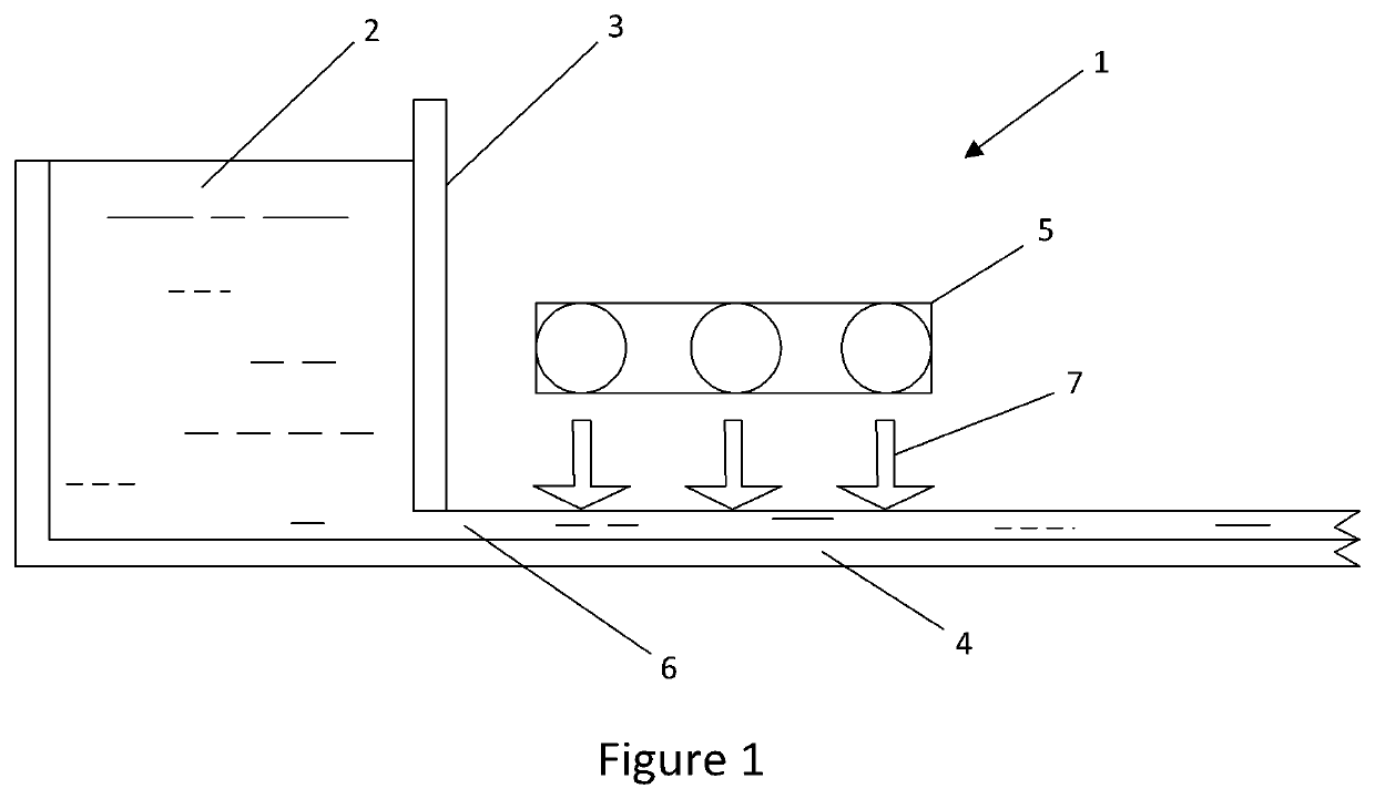
[0039]The invention will be described by way of examples employing ultraviolet (UV) radiation but it is to be appreciated that in appropriate circumstances that other forms of radiation may be employed. As light intensity decreases exponentially as it penetrates a liquid a system having a thin flow of liquid is desirable due to the increased efficiency and ability to treat contaminated or occluded liquids with low UV light transmissibility. To maintain treatment capacity, the speed at which the liquid flows through the system must be increased. However, pressure losses due to friction need to be minimised to avoid excessively increasing capital and operating costs.

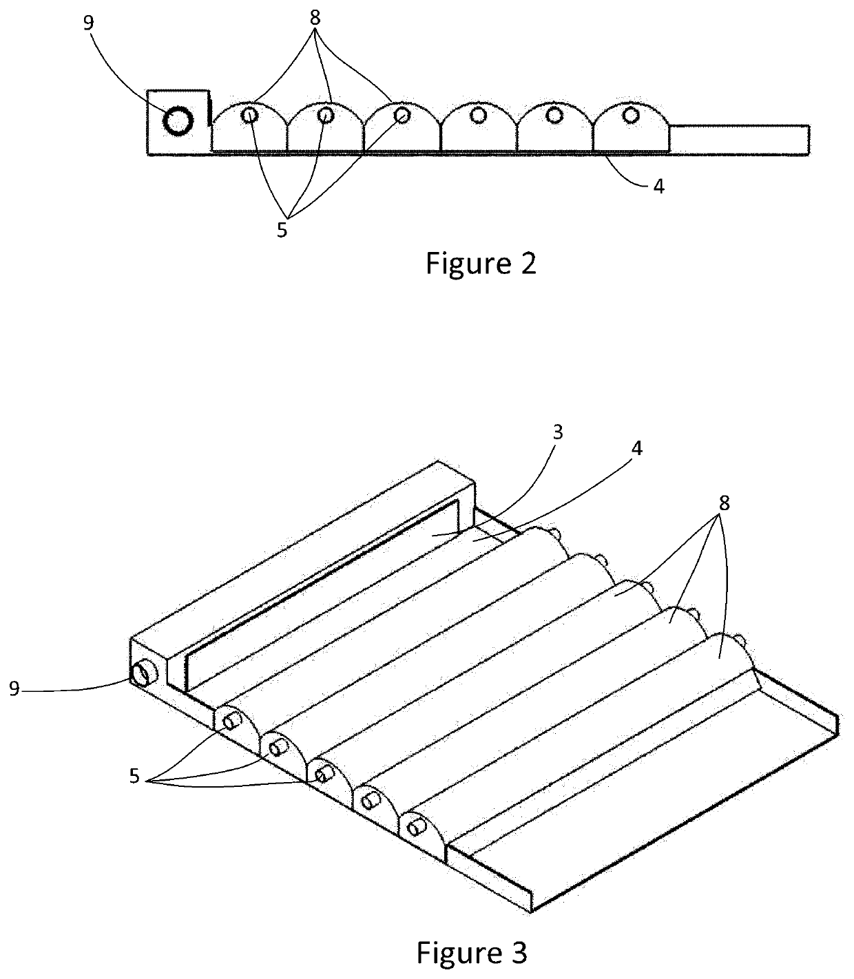
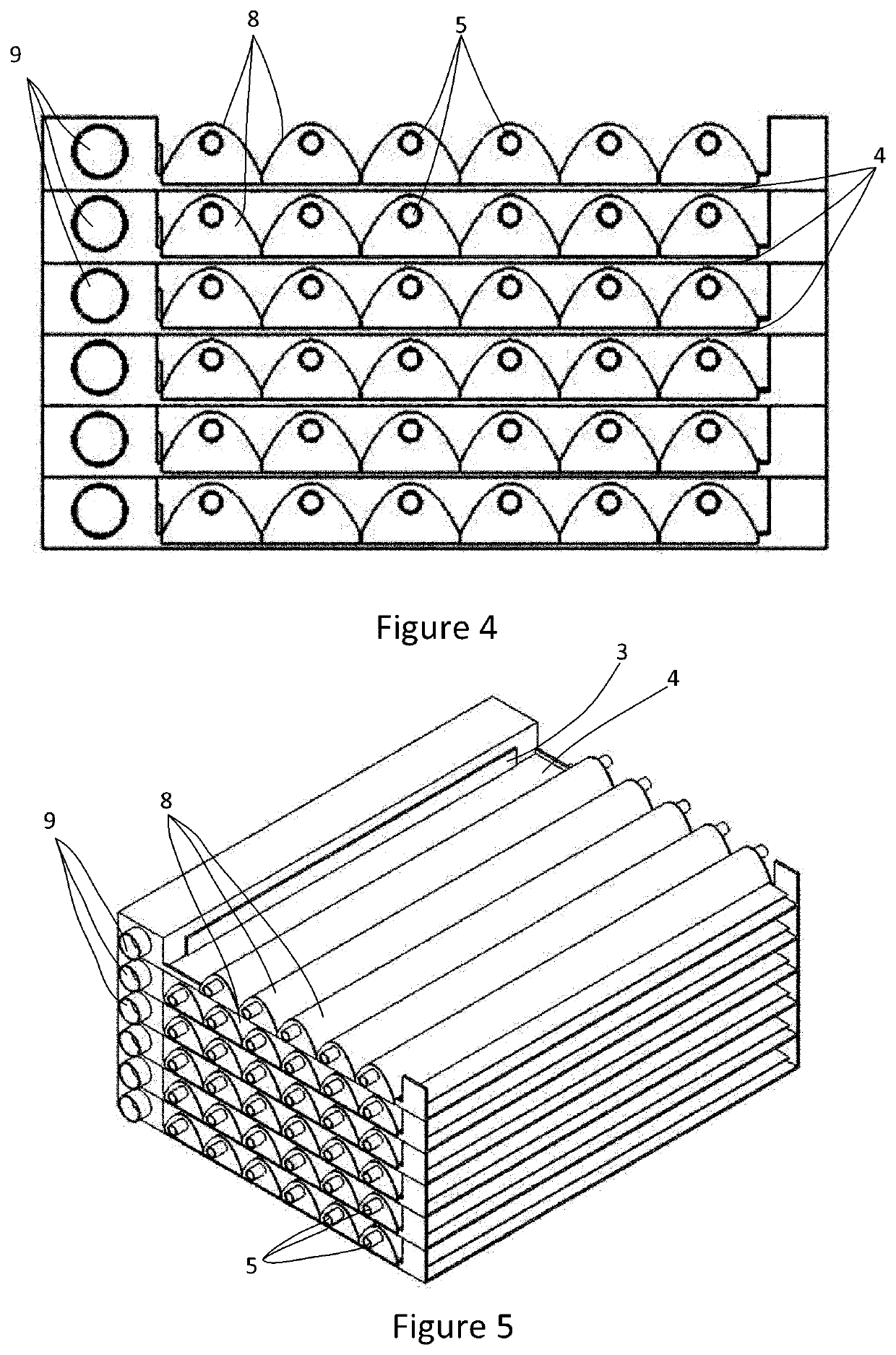
[0040]FIG. 1 shows a liquid treatment apparatus 1 according to an exemplary embodiment. The source 2 of a liquid to be treated may be a header tank or other reservoir that maintains a gravity liquid pressure that provides the driving energy for the flow exiting 2. A gate 3 is used to restrict the flow of liquid exiting fro...


PUM


Abstract

A method and apparatus for treating a liquid using ultraviolet radiation. A thin flow of liquid in a supercritical flow is irradiated by at least one radiation source external to the thin flow. The flow may desirably have a Froude number greater than 3 and a velocity greater than 0.8 m / s. The apparatus for treating a liquid including may have a reservoir supplying liquid though a slot into an open channel to generate a thin flow of liquid having a supercritical flow along the channel with at least one radiation source external to the thin flow to irradiate the thin flow.

Description

FIELD[0001]This invention relates to a method and apparatus for treating a liquid using ultraviolet radiation.BACKGROUND[0002]Ultraviolet radiation is known to be an effective germicidal agent. Currently, applications utilising ultraviolet light treatment include the disinfection of liquids.[0003]Systems employing UV radiation sources provided in quartz tubes within a flow of liquid to be treated are widely employed. Any system where the ultraviolet radiation source is submerged in the liquid has electrical connection and associated waterproofing complexities. These systems also typically require a quartz barrier to protect the ultraviolet light source from the liquid, with the barrier absorbing some of the ultraviolet radiation and reducing the overall efficiency. These quartz tubes also require periodic cleaning. These complexities add to the cost of constructing and maintaining prior art systems. Pressure losses are also incurred due to the friction of the flow against the walls ...

Claims


Application Information

Patent Timeline
IPC IPC(8): C02F1/32
CPCC02F1/325C02F2303/04C02F2301/02C02F2201/3227C02F2201/3221C02F2201/3222C02F2209/40C02F1/32B01J19/123A61L2/10C02F2103/001C02F2201/3228
Inventor SHILTON, ANDREW NICHOLAS
Owner NOVOLABS LTD
Learn More