System, an arrangement and method for heating and cooling

a technology arrangement, applied in the field of can solve the problems of complex and unreliable heating and cooling system, inability to decide between heating and cooling, and complex prior art system

Pending Publication Date: 2021-06-03
QUANTITATIVE HEAT OY
View PDF0 Cites 4 Cited by
  • Summary
  • Abstract
  • Description
  • Claims
  • Application Information

AI Technical Summary

Benefits of technology

[0090]An advantage of the invention is that the system, arrangement and method combines district and local heating as well as heating and cooling. The invention allows different buildings and building spaces to be heated and cooled individually and further to exchange thermal energy with each other. Therefore, the different buildings or building spaces may utilize thermal energy of each other and only the net or overall thermal energy needed or in excess may be extracted or supplied to or from, respectively, the geothermal heat exchanger which is connected to the buildings or building spaces. Further, the geothermal heat exchanger may be used in the heat extraction mode when net thermal energy need of the buildings or building spaces is negative, and in heat charging mode when net thermal energy need of the buildings or building spaces is positive. In the heat extraction mode heat energy is supplied from the ground to the geothermal heat exchanger and further to the secondary thermal network. In the heat charging mode heat energy is supplied from the secondary thermal network to the geothermal heat exchanger and further to the ground.

Problems solved by technology

The disadvantage of prior art centralized heating or cooling systems is that they are complex and do not take into account individual needs of different buildings.
This means, that when centralized heating is carried out, all the buildings receive heat energy via the pipe network and each building may only decide how much heat energy it will utilize.
Similarly, when centralized cooling is carried out, all the buildings receive cooling energy via the pipe network and each building may only decide how much cooling energy it will utilize.
Accordingly, the buildings cannot decide between the heating and cooling.
This makes the prior art systems even more complex.

Method used


Image

  • System, an arrangement and method for heating and cooling
  • System, an arrangement and method for heating and cooling
  • System, an arrangement and method for heating and cooling

Examples


Embodiment Construction

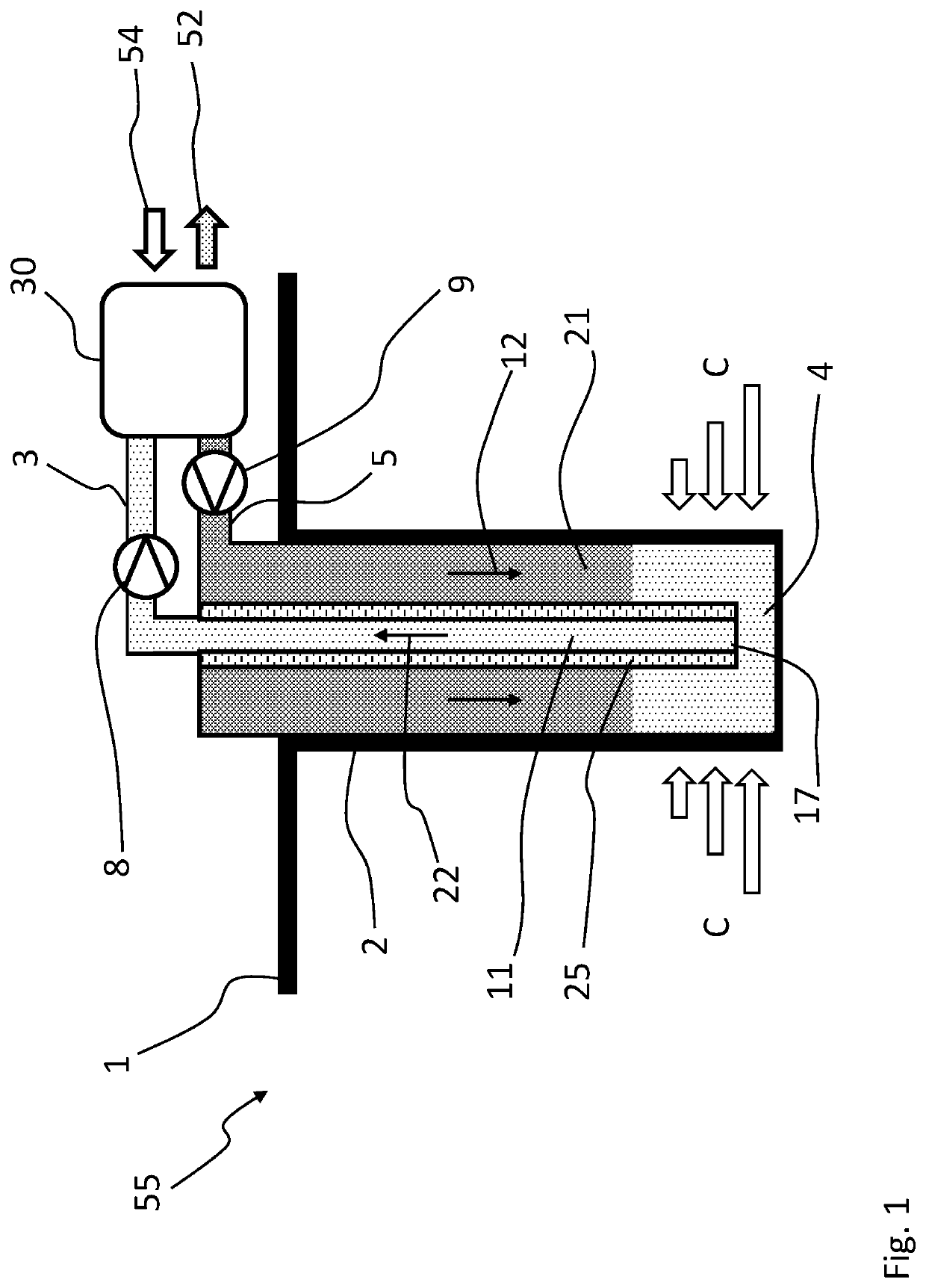
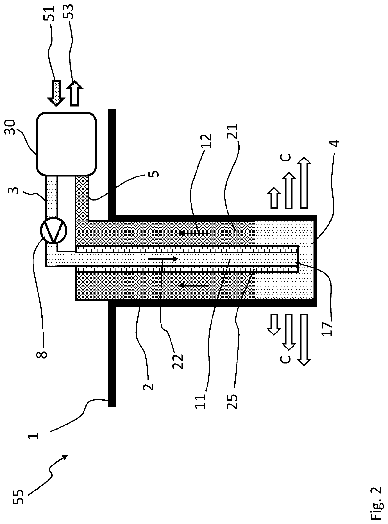
[0104]FIG. 1 shows a geothermal heating apparatus. The geothermal heating apparatus comprises a ground hole 2 or bore hole provided to the ground and extending downwards into the ground from the ground surface 1. The ground hole 2 may be formed by drilling or some other excavating method.

[0105]In the context of the present application the depth of the ground hole 2 from the ground surface 1 may be at least 300 m, or at least 500 m, or between 300 m and 3000 m, or between 500 m and 2500 m. Alternatively or additionally, the ground hole 2 extends into the ground to a depth in which the temperature is at least 15° C., or approximately 20° C., or at least 20° C.

[0106]The ground hole 2 may extend to a depth under the water table in the ground, meaning through the water table. Alternatively, the ground hole 2 may extend to a depth above the water table in the ground.

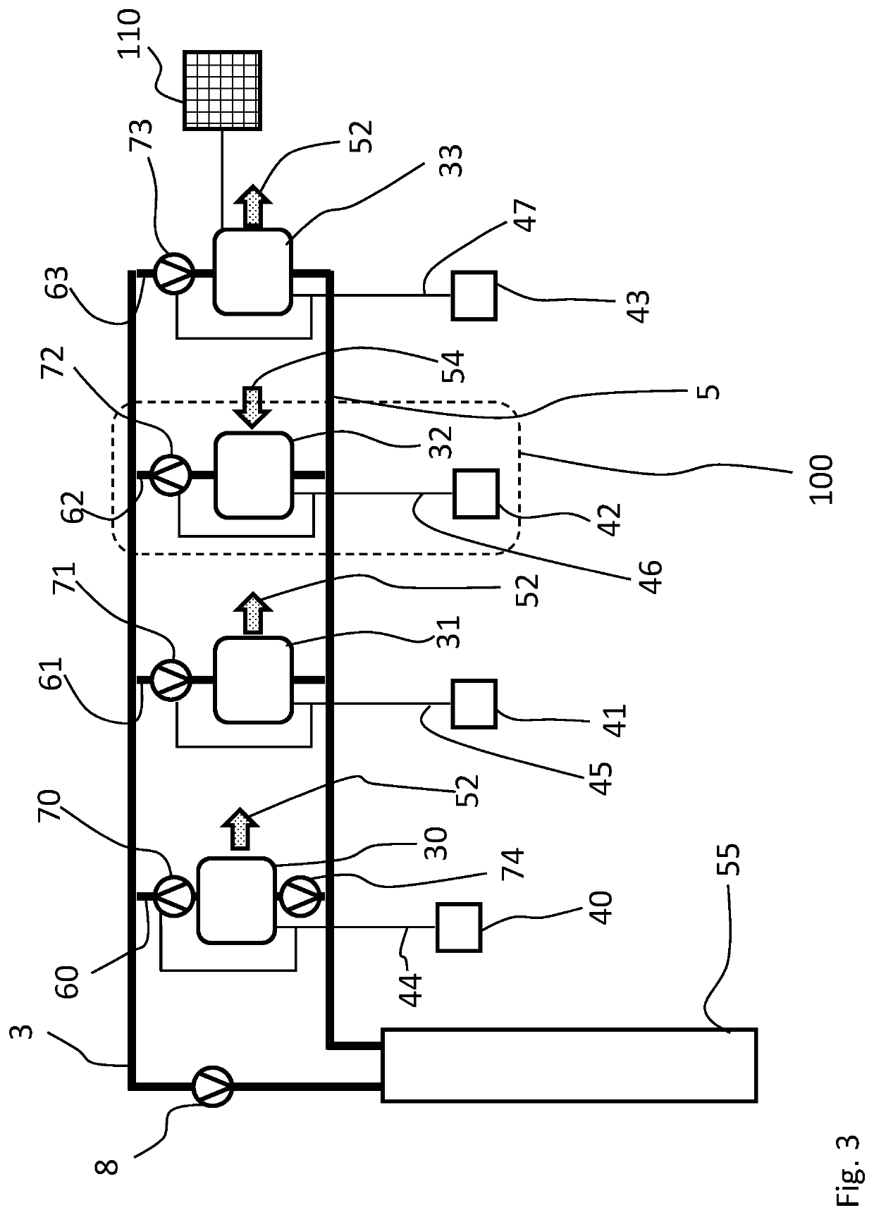
[0107]It should be noted that in the figures similar structural part and structures are denoted with same reference numerals...


PUM


Abstract

A system, an arrangement and method for heating and cooling of several building spaces-or buildings includes two or more building spaces or buildings, and a secondary thermal network including a supply line and a return line. The arrangement further comprises two or more building connections arranged parallel to each other and between the supply line and provided in connection with the two or more building spaces or buildings, a ground hole and a geothermal heat exchanger provided to the ground hole and arranged in connection with the secondary thermal network.

Description

FIELD OF THE INVENTION[0001]The present invention relates to a heating and cooling system and more particularly to a heating and cooling system and more particularly according to the preamble of claim 1. The present invention also relates to an arrangement for heating and cooling of several building spaces or buildings, and more particularly to an arrangement according to the preamble of claim 10. The present invention further relates to a method heating and cooling of several building spaces or buildings, and more particularly to a method according to the preamble of claim 18.BACKGROUND OF THE INVENTION[0002]District heating and cooling, or centralized heating and cooling, are commonly known systems in which heat energy or cooling energy is produced in a centralized plant or source and distributed via a pipe network to several buildings. The source of heat energy in centralized heating systems is an energy plant or an industrial plant which can produce heat energy for the distribut...

Claims


Application Information

Patent Timeline
Patent Type & Authority Applications(United States)
IPC IPC(8): F25B30/06F24T10/17F24D18/00
CPCF25B30/06F24F5/0046F24T10/17F25B25/005F24D2200/11F24D2200/123F24D2200/14F24D10/00F24D3/18F24D15/04F24F2005/0067F24F5/0096F24T10/15F24T10/20F24T50/00F24T2010/50F24T2010/56Y02B30/12Y02A30/272Y02P80/14Y02B10/20Y02B10/70Y02B10/40F24D2101/40F24D18/00F24D2103/13F24D2105/00Y02E10/10F25B2313/002
Inventor NIEMI, RAMI
Owner QUANTITATIVE HEAT OY
Why Eureka
Try Eureka