Downhole Tubular Milling Apparatus, Especially Suitable for Deployment on Coiled Tubing

a tubular milling and tubular technology, applied in the direction of borehole/well accessories, earthwork drilling and mining, etc., can solve the problems of limiting the use of prior art casing cutting and/or milling tools

Active Publication Date: 2021-07-22
ABRADO INC
View PDF0 Cites 1 Cited by
  • Summary
  • Abstract
  • Description
  • Claims
  • Application Information

AI Technical Summary

Benefits of technology

The present invention is an apparatus for use in drilling oil wells. Its main feature is a piston that can be moved by fluid flow to perform various functions such as cutting and cleaning tubulars. The apparatus can be attached to a workstring and can be easily moved through narrow bores. The cutter bases can be angled for easier access. The apparatus can be controlled using an interchangeable jet to control fluid flow. The unique design allows for easy movement and retrieval of the apparatus. Overall, this invention provides a flexible and efficient tool for drilling oil wells.

Problems solved by technology

However, prior art casing cutting and / or milling tools exhibit various limitations when deployed on coiled tubing.

Method used


Image

  • Downhole Tubular Milling Apparatus, Especially Suitable for Deployment on Coiled Tubing
  • Downhole Tubular Milling Apparatus, Especially Suitable for Deployment on Coiled Tubing
  • Downhole Tubular Milling Apparatus, Especially Suitable for Deployment on Coiled Tubing

Examples


Embodiment Construction

)

[0020]While various apparatus can embody the principles of the present invention, with reference to the drawings some of the presently preferred embodiments can be described.

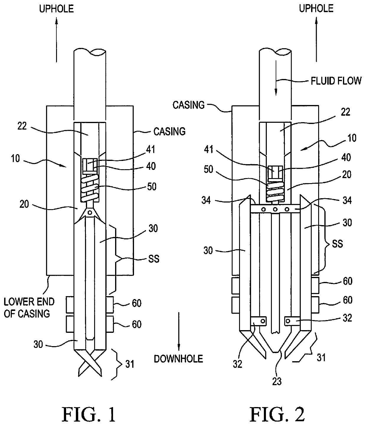
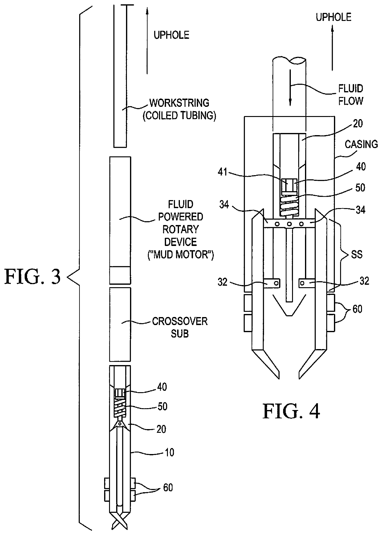
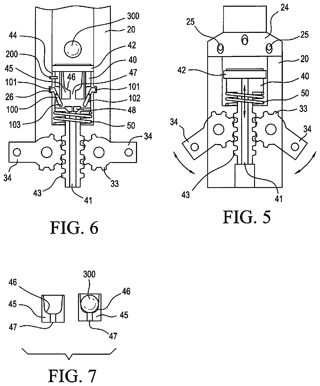
[0021]As can be seen in FIGS. 1 and 2, apparatus 10 comprises a main body 20, which is generally elongated with a longitudinal bore 22 therethrough. Main body 20 comprises a means for attachment to a tubular string, which may be a coil tubing string, at its upper or uphole end. Uphole / downhole relative direction and orientation is noted on the drawings.

[0022]A plurality of cutter bases 30 are hingedly attached to main body 20 by a plurality of link arms 32, the uppermost of which comprises a plurality of operating arms 34 as will be later described. As readily understood from the drawings, link arms 32 and operating arms 34 are preferably of substantially equal length, so that cutter bases 30 are substantially parallel to main body 20, as cutter bases 30 move from a first, substantially retracted position as in...


PUM


Abstract

An apparatus for cutting and / or milling of tubulars in a wellbore, especially using coiled tubing. An elongated main body has a longitudinal bore, with a piston slidably positioned in the bore. The piston is connected to one or more operating arms which are rotatably connected to the main body. The connection between the piston and the operating arms may be a pinned connection or a geared connection, both of which provide for a positive connection between the piston and the operating arms. Cutter bases are connected to the cutter arms, with a number of cutters mounted to the cutter bases. Fluid flow down the coiled tubing and through the main body bore pushes the piston downwardly, opening the operating arms and cutter bases and permitting the apparatus to be pulled up into the lower end of a tubular string for cutting and / or milling.

Description

CROSS REFERENCE TO RELATED APPLICATIONS[0001]This non-provisional patent application is a continuation application of and claims priority to pending U.S. patent application Ser. No. 15 / 758,985, filed Mar. 9, 2018; which was a United States national phase entry application from PCT / US2016 / 051780, filed Sep. 14, 2016; and claims priority to U.S. provisional patent application Ser. No. 62 / 218,953, filed Sep. 15, 2015, for all purposes. The disclosure of that provisional patent application is incorporated herein, to the extent not inconsistent with this application.BACKGROUND—FIELD OF THE INVENTION[0002]The apparatus embodying the principles of the present invention is used in connection with the cutting and / or milling of tubulars downhole, typically those in oil and gas wells (“wells”). In particular, the apparatus may be used to mill a section of a tubular, such as a casing string, where the casing string has a downwardly-facing end at some depth in the wellbore.[0003]As is known in t...

Claims


Application Information

Patent Timeline
Patent Type & Authority Applications(United States)
IPC IPC(8): E21B29/00
CPCE21B29/005E21B29/002
Inventor RUTTLEY, DAVID J.
Owner ABRADO INC
Why Eureka
Try Eureka