
Sheet handling apparatus

a technology of paper handling and stacking, which is applied in the direction of thin material handling, coin/currency accepting devices, instruments, etc., can solve the problem of inconvenient stacking and transportation

Active Publication Date: 2007-08-14
UNIVERSAL ENTERTAINMENT CORP
View PDF14 Cites 4 Cited by
  • Summary
  • Abstract
  • Description
  • Claims
  • Application Information

AI Technical Summary

Benefits of technology

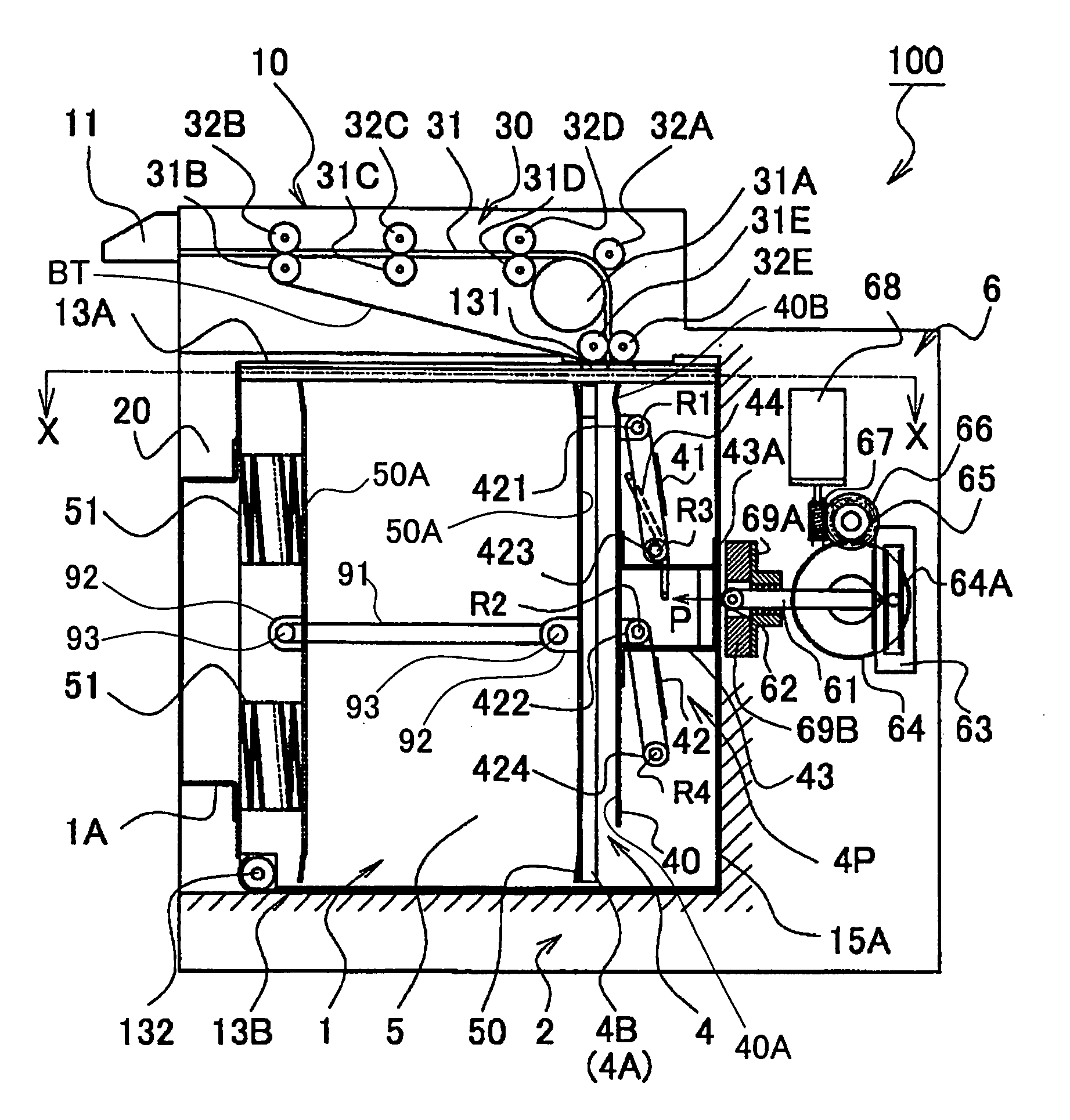
[0010]The present invention is done taking the above situation into consideration, and the object of the present invention is to provide a sheet handling apparatus having a light sheet receiving unit with a small size which is detachably arranged in a main unit, thereby there is no need to arrange a specific sheet take-in device such as sheet sending rollers, based on that a push device, which comprises a simple link mechanism surely pushing sheets fed from a sheet feed device in the sheet receiving unit, is arranged in the sheet receiving unit, and a drive device for driving the link mechanism is arranged in the main unit.
[0021]As mentioned, in the sheet handling apparatus, the sheet push plate draws and separates the sheet from the sheet feed device and pushes the separated sheet to the sheet support plane while retaining a parallel relation between a sheet push plane of the sheet push plate and the sheet support plane of the sheet support plate. Thereby, there is no need to independently provide a mechanism for drawing and separating the sheet from the sheet feed device and a mechanism for parallel moving the sheet toward the sheet support plane of the sheet support plate. As a result, the sheet can be drawn and separated from the sheet feed device and can be surely moved to the sheet support plane of the sheet support plate, through the sheet push plate and the push device.
[0022]Further, even if the sheet fed to the sheet receiving unit through the sheet feed device does not fall in the sheet receiving unit by natural fall thereof, based on that the sheet push plate is rotated downward while retaining a parallel relation between a sheet push plane of the sheet push plate and the sheet support plane of the sheet support plate, thereby the sheet push plate can give a downward force to the sheet and can stack the sheet in the sheet receiving unit after reforming the sheet in a plain state.
[0023]As mentioned, in order to surely take the sheet fed from the sheet feed device into the sheet receiving unit, there is no need to provide a sheet take-in mechanism constructed from feed rollers and sliders and a drive source for driving the sheet take-in mechanism. Therefore, the sheet receiving unit can be simply constructed and cost thereof can be reduced.
[0033]According to the above sheet handling apparatus, when a rear end of the sheet fed to the sheet receiving unit is held by a roller pair positioned in a final stage among the roller pairs, the sheet push plate draws and separates the rear end of the sheet from the roller pair in the final stage and pushes the sheet to the sheet support plane of the sheet support plate. Thereby, the sheet push plate draws and separates the sheet fed to the sheet receiving unit from the sheet feed device and pushes the sheet to the sheet support plane of the sheet support plate. As mentioned, in the sheet handling apparatus, the sheet push plate draws and separates the sheet from the sheet feed device and pushes the separated sheet to the sheet support plane, thereby there is no need to independently provide a mechanism for drawing and separating the sheet from the sheet feed device and a mechanism for parallel move the sheet toward the sheet support plane of the sheet support plate. As a result, the sheet can be drawn and separated from the sheet feed device and can be surely moved to the sheet support plane of the sheet support plate, through the sheet push plate and the push device.
[0034]As mentioned, in order to surely take the sheet fed from the sheet feed device into the sheet receiving unit, there is no need to provide a sheet take-in mechanism constructed from feed rollers and sliders and a drive source for driving the sheet take-in mechanism. Therefore, the sheet receiving unit can be simply constructed and cost thereof can be reduced.

Problems solved by technology

Due to this, the stacker becomes heavier and bigger, as a result, it is very inconvenient to carry the stacker.

Method used


Image

  • Sheet handling apparatus
  • Sheet handling apparatus
  • Sheet handling apparatus

Examples


first embodiment

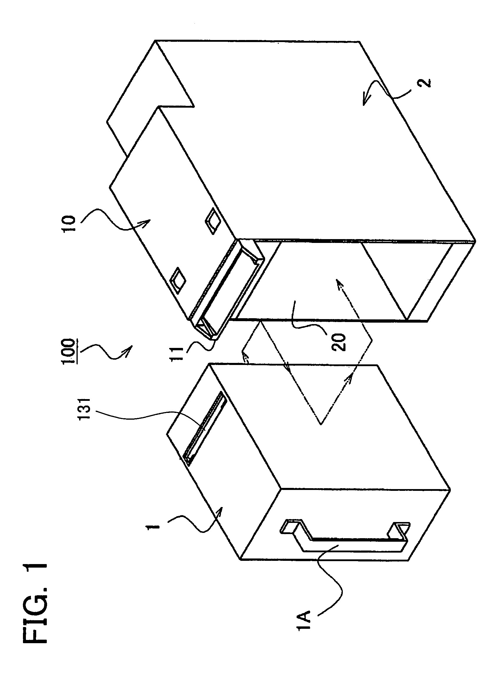
[0052]FIG. 1 is an outline view roughly showing a bill handling apparatus in the In FIG. 1, a bill handling apparatus 100 is constructed from a bill validating unit 10 which operates as a bill validating device for validating whether bills received from outside thereof are valid or not, and a main unit 1 in which a bill receiving device 1 (abbreviated as “stacker 1” hereinafter), which receives many bills in a pile, is arranged. The stacker 1 is made detachable in the main unit 2 of the bill handling apparatus 100.

[0053]In FIG. 1, a handle 1A is fixed to the rear side of the stacker 1 formed in a box-like shape. The handle 1A is utilized when the stacker 1 is taken from the main unit 2 or when the stacker 1 is carried out. In the bill validating unit 10, a bill insertion slot 11 is formed at an entrance thereof. And under the bill insertion slot 11, an opening 20 for inserting the stacker 1 is formed in the main unit 2.

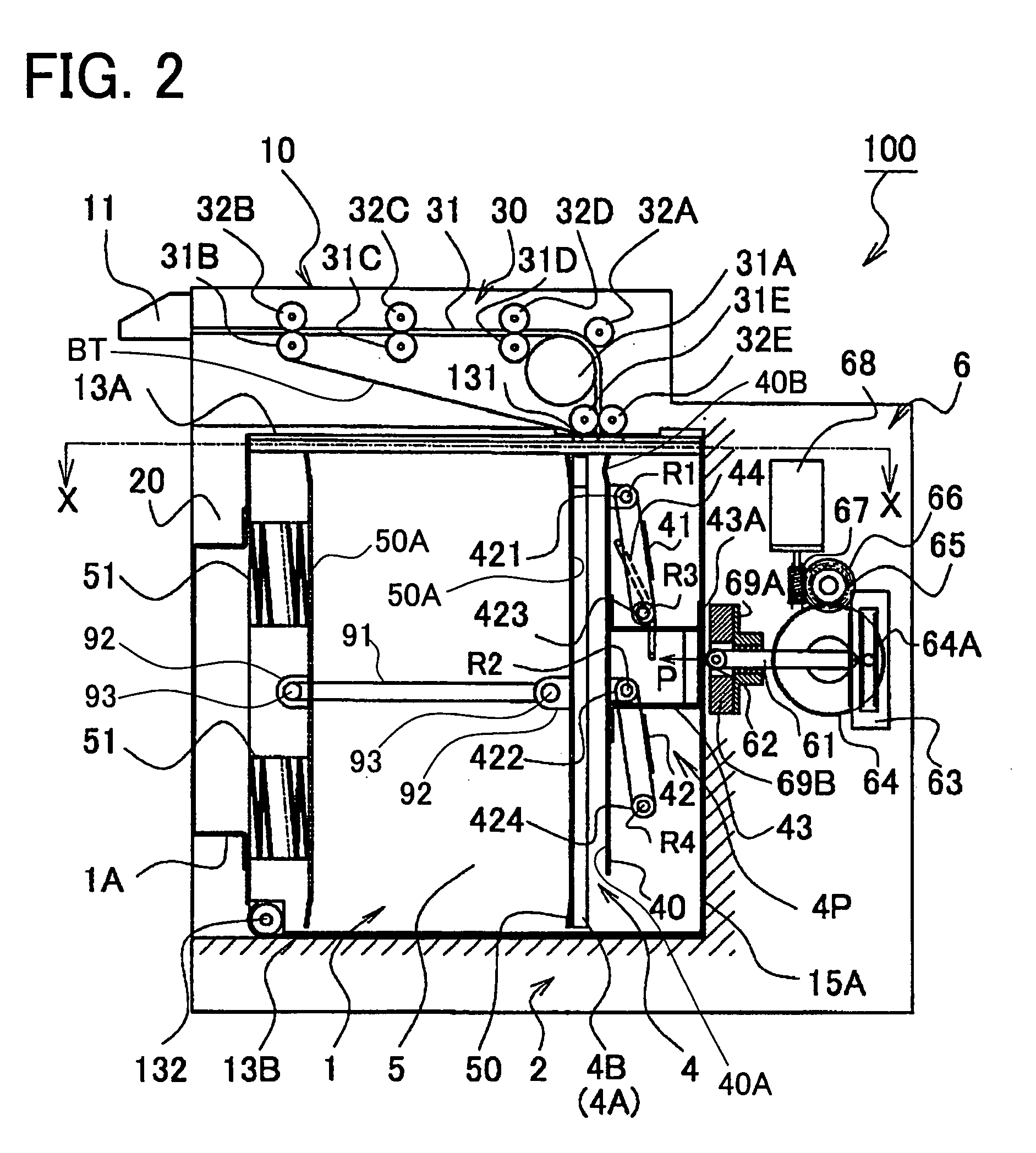
[0054]FIG. 2 is a longitudinal sectional view of the bill handl...

second embodiment

[0117]In the bill push-in device 7 the magnetic solenoid 71 is driven and controlled by an instruction from the control unit (not shown). As mentioned, based on driving and controlling the magnetic solenoid 71, the parallel crank mechanism 4P (see FIG. 2) connected to the bill push-in device 7 can be opened and closed.

[0118]The bill push-in device 7 of the second embodiment has a simple construction and can directly open and close the parallel crank mechanism 4P (see FIG. 2). Thereby, the bill push-in device 7 can be simply constructed. Further, the plunger 72 is arranged so as to be able to enter in and go out from the stacker 1 and is also arranged along the same direction as the insert and pull direction of the stacker 1 in the bill handling apparatus 100. Accordingly, the push-in plate 40 can be moved from the bill guide part 4 to the bill piling part 5 without providing the bill push-in device 7 in the stacker 1.

[0119]Next, the bill push-in device 8 utilized for operating the ...


PUM


Abstract

In the bill handling apparatus 100, there are provided the bill validating unit 10 which judges whether the bill received from outside is valid or not, the stacker 1 which is detachable with the main unit 2 and receives the bill judged as valid by the bill validating unit 10, the bill feed unit 30 which feeds the bill from the bill validating unit 10 in the length direction of the bill and the bill guide part 4 which temporarily holds the bill discharged from the bill feed unit 30. When the force P is exerted to the press force receiving plate 43, the push-in late 40 is contacted to the bill by the parallel crank mechanism 4P, thereby the bill is moved toward the bill support plate 50, thereafter the bill is stacked in the bill piling part 5 between the partition walls 4A, 4B and the bill support plate 50.

Description

CROSS-REFERENCE TO THE RELATED APPLICATION[0001]This application is based upon and claims a priority from the prior Japanese Patent Application No. 2003-118203 filed on Apr. 23, 2003, the entire contents of which are incorporated herein by reference.BACKGROUND OF THE INVENTION[0002]1. Field of the Invention[0003]The present invention relates to a paper sheet handling apparatus which can handle paper sheets such as bills and the like. Here, as paper sheets which are handled in the paper sheet handling apparatus according to the present invention, there will be conceivable bills. And the paper sheet handling apparatus can be applied to gaming machines such as Japanese Pachinko machines, slot machines or vending machines (abbreviated as “gaming machines and the like” hereinafter).[0004]2. Description of Related Art[0005]Conventionally, it is known a bill handling apparatus, installed in the gaming machines and the like, which are provided with a bill validating unit for validating whet...

Claims


Application Information

Patent Timeline
IPC IPC(8): B65H29/38G07D9/00B65H29/46B65H31/06G07D11/00G07F7/04
CPCB65H29/38B65H31/06G07D11/0012G07F7/04B65H31/22B65H2405/20G07D11/13
Inventor YOSHIOKA, KAZUEIFUJIMOTO, JUN
Owner UNIVERSAL ENTERTAINMENT CORP
Learn More