
Kinematic Mirror Mount Adjustment System

Inactive Publication Date: 2021-09-02
PHOTON VALLEY INC
View PDF1 Cites 1 Cited by
  • Summary
  • Abstract
  • Description
  • Claims
  • Application Information

AI Technical Summary

Benefits of technology

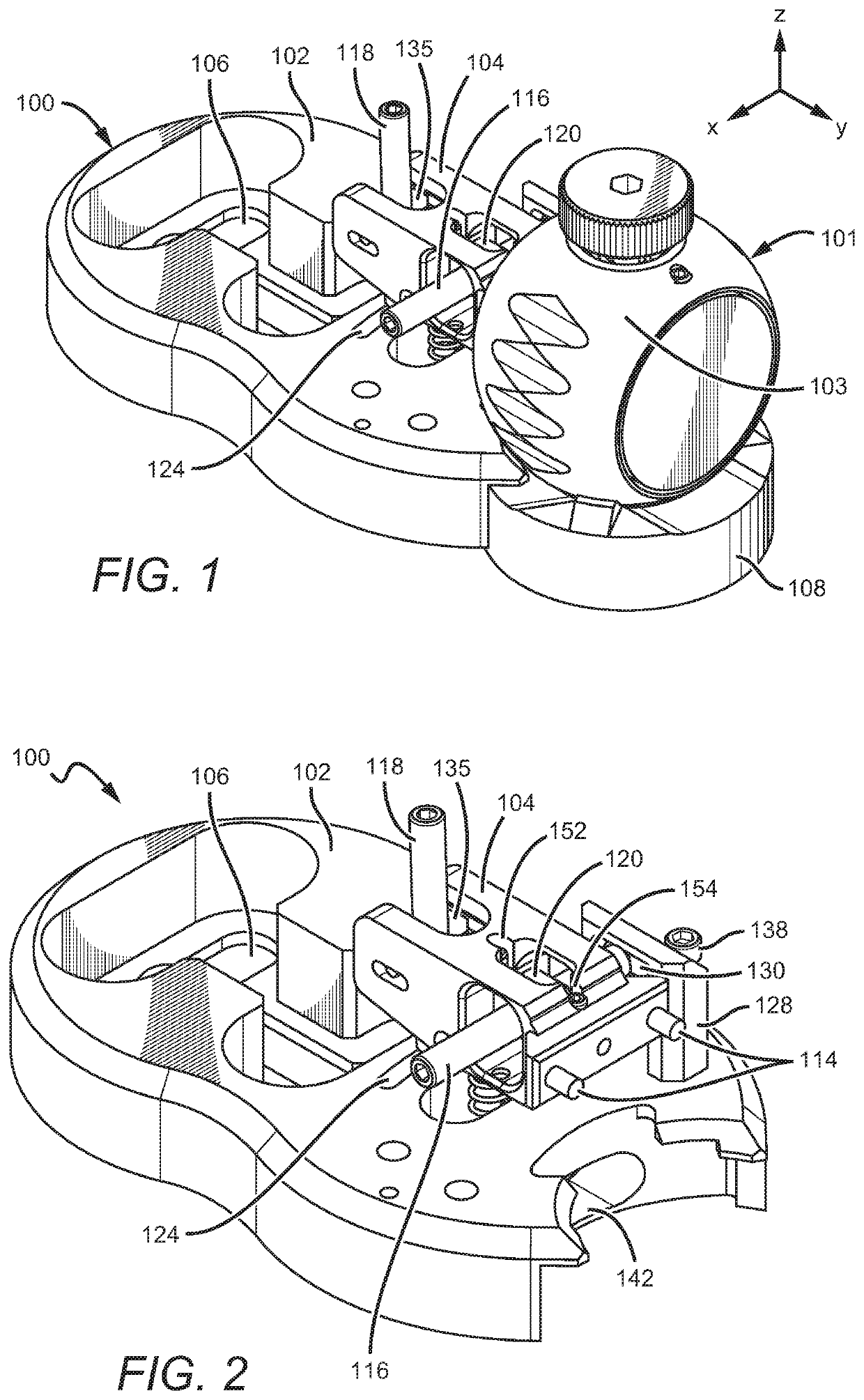
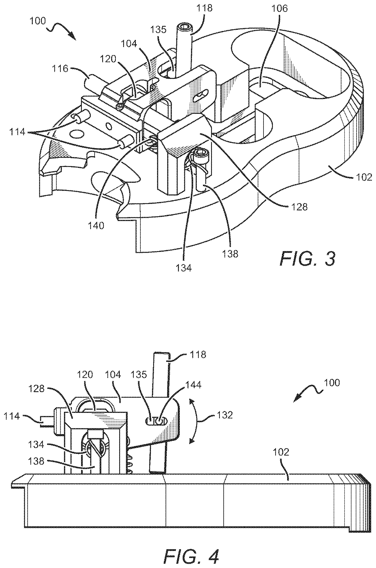
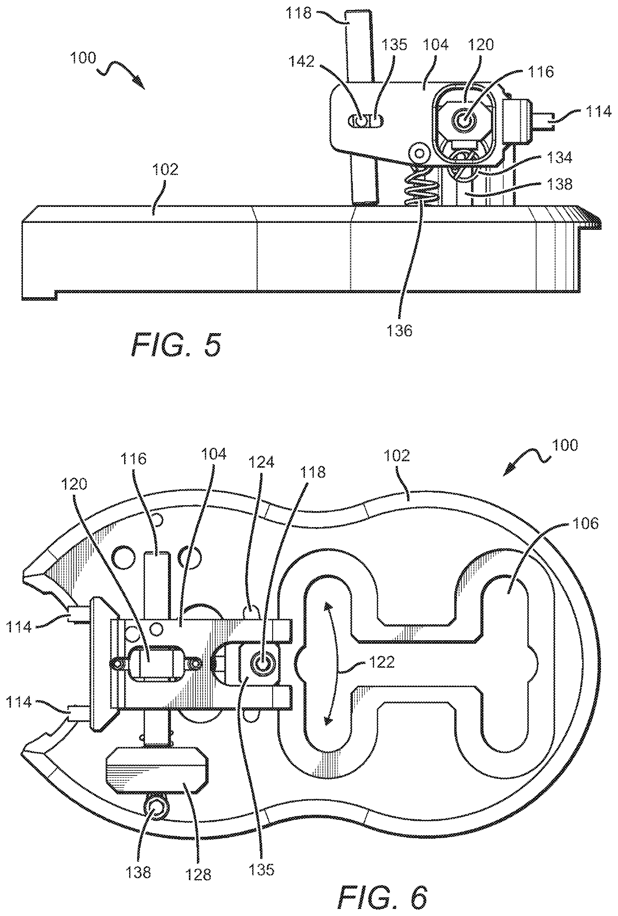
The present invention provides a new adjustment mechanism for kinematic mounts that pivot about a center point. This mechanism consists of a main body, a control frame, first and second control screws, and first and second screw harnesses. The first control screw is positioned at the end of the first control swab and connected to the control frame through a first screw harness. The second control screw is positioned at the end of the second control swab and connected to the control frame through a second screw harness. The main body and control frame can have elongated divts to allow for movement. The system also includes springs to pull the control frame towards the main body and a countersunk cutout for easy mounting. The technical effect of this invention is to provide an improved adjustment mechanism for kinematic mounts that can pivot about a center point.

Problems solved by technology

In the space of kinematic mounts for, e.g., mirrors or other optics equipment, innovation has been slow or nonexistent for many years.
Though many have improved on the current state of adjustment mechanisms over the years, none have reimagined the kinematic mount that those adjustment mechanisms work with.
The physical structure of the device in the '733 patent fails to consider a reimagined kinematic mount, and thus fails to solve problems associated with new types of kinematic mounts that operate on fundamentally different bases than the state of the art.
U.S. Pat. No. 9,329,028 to Bridges et al. describes mirror mounting systems having spherical or semispherical mounts, but because this patent again fails to contemplate new kinematic mounts that do not share many—if any—overlapping features with kinematic mounts as they currently exist.

Method used


Image

  • Kinematic Mirror Mount Adjustment System
  • Kinematic Mirror Mount Adjustment System
  • Kinematic Mirror Mount Adjustment System

Examples


Embodiment Construction

[0024]The following discussion provides example embodiments of the inventive subject matter. Although each embodiment represents a single combination of inventive elements, the inventive subject matter is considered to include all possible combinations of the disclosed elements. Thus, if one embodiment comprises elements A, B, and C, and a second embodiment comprises elements B and D, then the inventive subject matter is also considered to include other remaining combinations of A, B, C, or D, even if not explicitly disclosed.

[0025]As used in the description in this application and throughout the claims that follow, the meaning of “a,”“an,” and “the” includes plural reference unless the context clearly dictates otherwise. Also, as used in the description in this application, the meaning of “in” includes “in” and “on” unless the context clearly dictates otherwise.

[0026]Also, as used in this application, and unless the context dictates otherwise, the term “coupled to” is intended to i...


PUM


Abstract

Kinematic mounts are used frequently to hold objects such as mirrors, lenses, and other optical equipment. To adjust kinematic mounts, adjustment mechanisms are often required. Adjustment mechanisms can be used to make fine adjustments in applications where precision is required (e.g., laser system prototyping). Kinematic mounts that include never-before implemented form factors and structural elements require new adjustment solutions, and those solutions are described in this application. Adjustment mechanisms described in this application include a main body, a control frame, and control screws to adjust the orientation of the control frame. The control frame is coupled with a kinematic mount's housing, which rotates about a center of curvature of a bottom surface of the housing.

Description

FIELD OF THE INVENTION[0001]The field of the invention is kinematic mount adjustment mechanisms.BACKGROUND[0002]The background description includes information that may be useful in understanding the present invention. It is not an admission that any of the information provided in this application is prior art or relevant to the presently claimed invention, or that any publication specifically or implicitly referenced is prior art.[0003]In the space of kinematic mounts for, e.g., mirrors or other optics equipment, innovation has been slow or nonexistent for many years. Few have approached this field with novel new thoughts or ideas on how kinematic mounts and their associated position and orientation adjustment mechanisms can be reinvented. Though many have improved on the current state of adjustment mechanisms over the years, none have reimagined the kinematic mount that those adjustment mechanisms work with. There therefore remains a need to develop improved kinematic adjustment m...

Claims


Application Information

Patent Timeline
IPC IPC(8): F16M13/02G02B7/182
CPCF16M13/022G02B7/182F16M11/041G02B7/003G02B7/1825G02B7/00
Inventor CAMPBELL, JAMESGUERRERO, CHRISTOPHERCASTRO, DANIEL
Owner PHOTON VALLEY INC
Learn More