Housing assembly for a turbocharger and method for fixing multiple connections to a housing
Inactive Publication Date: 2020-02-06
BORG WARNER INC
View PDF0 Cites 1 Cited by
Summary
Abstract
Description
Claims
Application Information
AI Technical Summary
This helps you quickly interpret patents by identifying the three key elements:
Problems solved by technology
Method used
Benefits of technology
Benefits of technology
The invention is a housing assembly with a first and second connection openings that have flanges. The assembly includes a first connecting piece and a second connecting piece with flanges that prevent rotation. The housing also has a projection with an overhang, under which a locking part of the first flange is located. This design allows for secure mounting of at least two connecting pieces on the housing using a few hand movements. The housing can be securely fixed on narrow or difficult-to-access mounting locations. The first flange can have concave and convex regions along its periphery, and the flanges have corresponding geometries that prevent rotation. The housing can also have a third connection opening and a third connecting piece with a flange that overlaps with the second connecting piece. This simplifies the mounting of three connecting pieces on a single housing.
Problems solved by technology
This may prove to be complicated and time-consuming, depending on the installation location of the turbocharger.
Method used
Image
Click on the blue label to locate the original text in one second.
Reading with bidirectional positioning of images and text.
Examples
embodiment 1
[0048]2. The housing assembly , characterized in that the second flange (310) is fixedly connected to housing (100), in particular wherein the second flange (310) is fixed on the housing (100) via a screw connection.
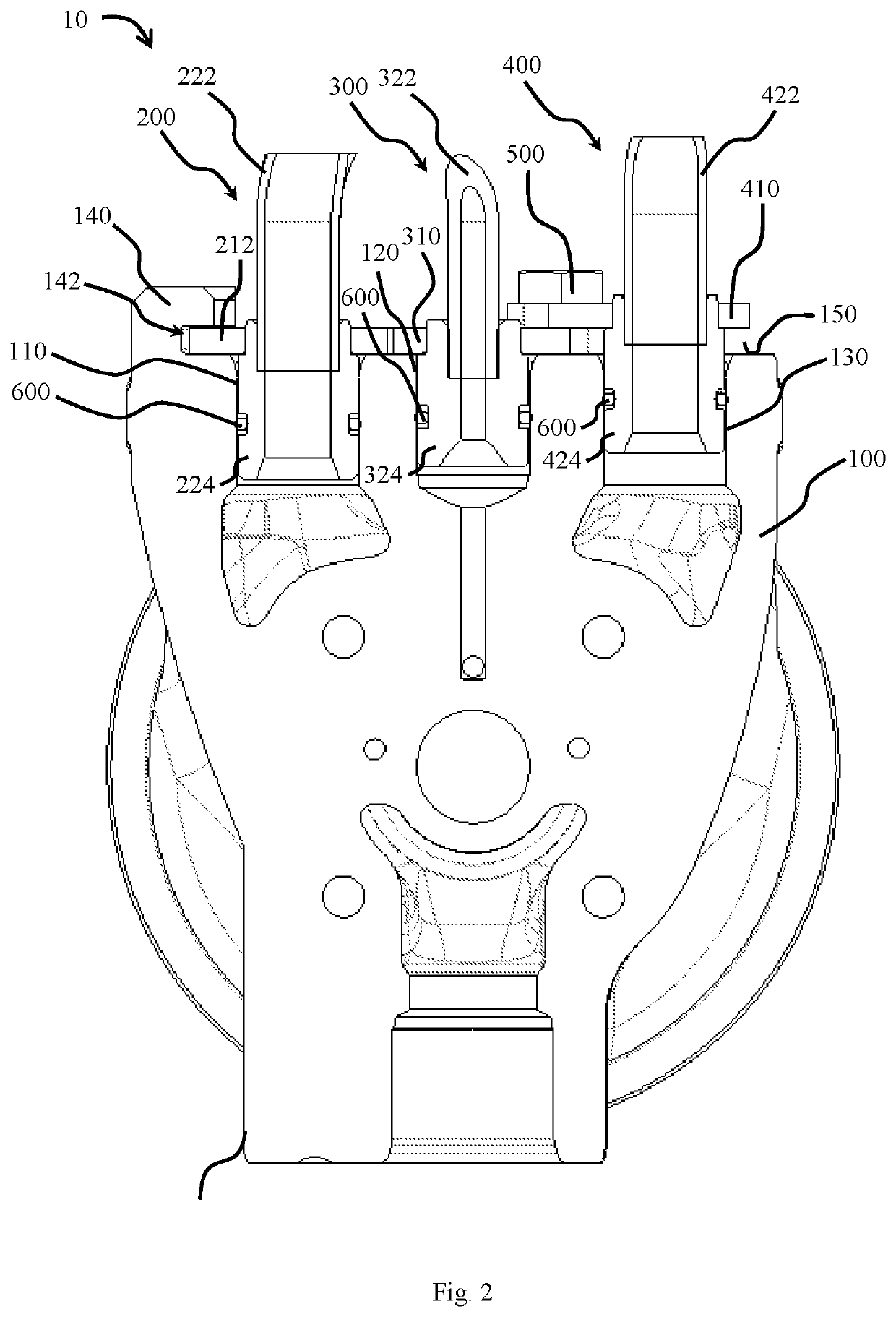
[0049]3. The housing assembly according to Embodiment 1 or Embodiment 2, characterized in that the second flange (310) has a borehole (312) through which a screw (500) extends which fixes the second flange (310) on the housing (100).
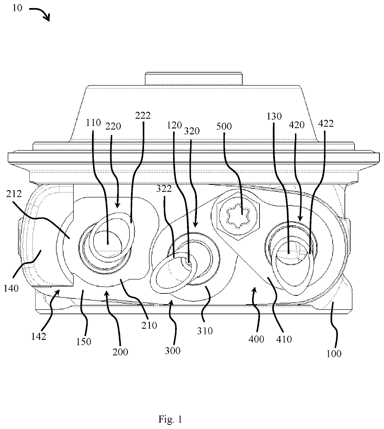
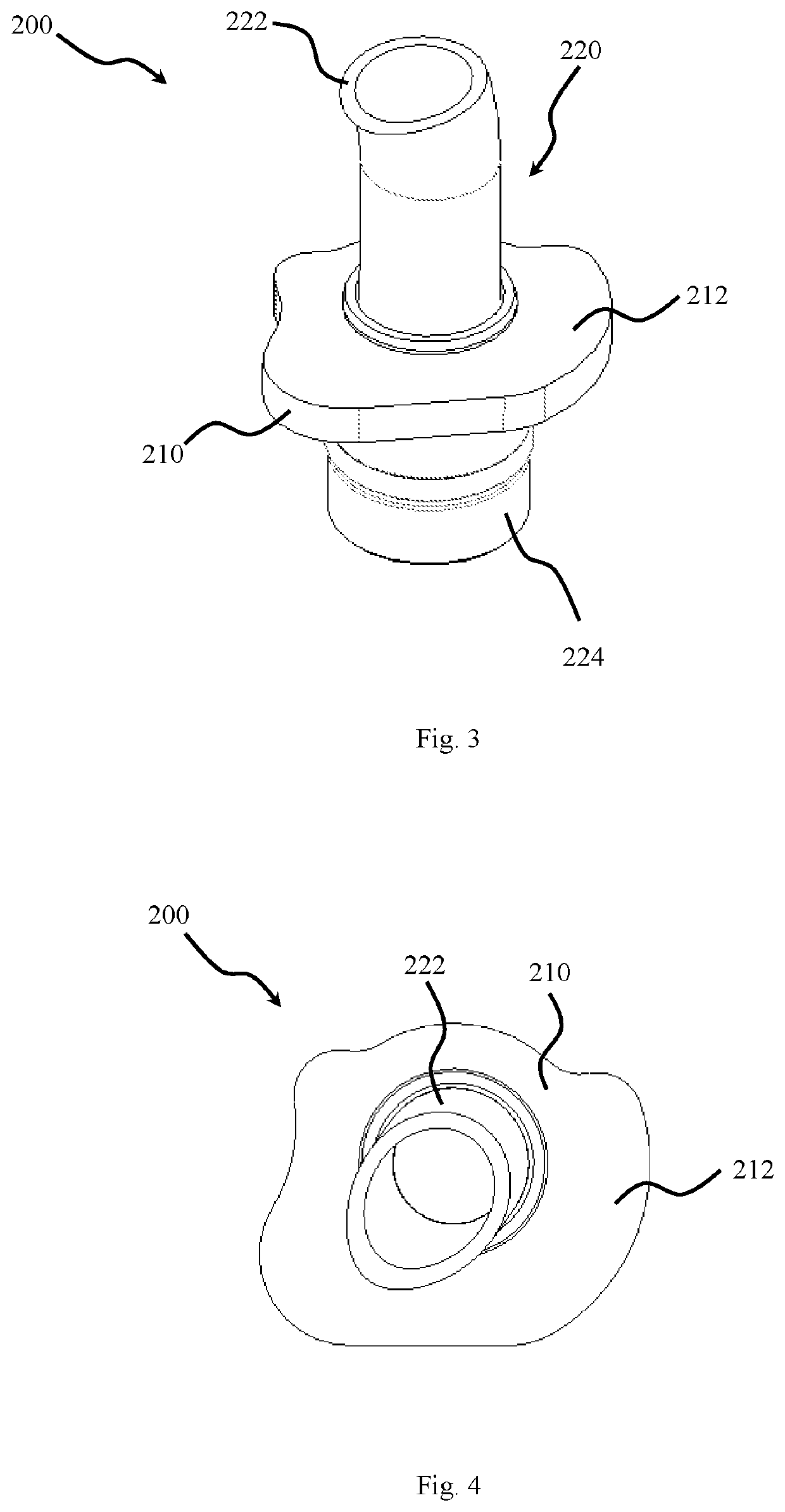
[0050]4. The housing assembly according to any one of the preceding embodiments, characterized in that the first connecting piece (200) and the second connecting piece (300) each comprise a tubular unit (220, 320), wherein the tubular units (220, 320) extend through the respective flange (210, 310) into the corresponding first and second connection openings (110, 120).
embodiment 4
[0051]5. The housing assembly , characterized in that the tubular units (220, 320) each comprise at least one part of a supply line (222, 322) and a connection sleeve (224, 324).
[0052]6. The housing assembly according to any one of the preceding embodiments, characterized in that a seal (600) is arranged in the respective connection openings (110, 120) between the connecting pieces (200, 300) and the housing wall, in particular wherein the seal (600) is an O-ring.
[0053]7. The housing assembly according to any one of the preceding embodiments, characterized in that the first and second connection openings (110, 120) are arranged in a plane, or characterized in that the first and second connection openings (110, 120) are arranged in two planes arranged spaced apart from one another and parallel to one another.
embodiment 7
[0054]8. The housing assembly , first alternative, characterized in that the housing (100) has a flat lateral surface (150) which lies in the plane, and wherein the first and second connection openings (110, 120) are arranged in the lateral surface (150).
[0055]9. The housing assembly according to any one of the preceding embodiments, characterized in that the first connecting piece (200) and the first flange (210) are configured in such a way that the first connecting piece (200) may be inserted into the first connection opening (110) during the mounting of the housing assembly (10) and may be subsequently turned so that the locking part (212) of the first flange (210) is rotated under the overhang (142).
PUM
Abstract
A housing assembly comprising a housing that has at least one first connection opening and one second connection opening, a first connecting piece with a first flange and a second connecting piece with a second flange. The first connecting piece is connected to the first connection opening and the second connecting piece is connected to the second connection opening. The housing additionally has a projection with an overhang. The A locking part of the first flange is arranged in locking engagement with the overhang, and the first flange and the second flange are configured in such a way and arranged with respect to one another that a turning of the first flange is prevented by the second flange. A corresponding method of fixing multiple connections to a housing is also provided.
Description
FIELD OF THE INVENTION[0001]The present invention relates to a housing assembly for a turbocharger.BACKGROUND INFORMATION[0002]Increasingly more vehicles of the more recent generation are equipped with charging devices. In order to satisfy target demands and legal requirements, it is imperative to promote development in the complete drive train and also to optimize the individual components as well as the system as a whole with respect to their reliability and efficiency.[0003]Exhaust gas turbochargers are known, for example, in which a turbine with a turbine wheel is driven by the exhaust gas flow of the internal combustion engine. A compressor wheel, which is arranged with a turbine wheel on a mutual shaft, compresses the fresh air taken in for the engine. By this means, the air or oxygen amount is increased that is available to the engine for combustion, which in turn leads to an increased output of the internal combustion engine.[0004]A bearing housing is arranged between the tu...
Claims
Application Information
Patent Timeline
Application Date:The date an application was filed.
Publication Date:The date a patent or application was officially published.
First Publication Date:The earliest publication date of a patent with the same application number.
Issue Date:Publication date of the patent grant document.
PCT Entry Date:The Entry date of PCT National Phase.
Estimated Expiry Date:The statutory expiry date of a patent right according to the Patent Law, and it is the longest term of protection that the patent right can achieve without the termination of the patent right due to other reasons(Term extension factor has been taken into account ).
Invalid Date:Actual expiry date is based on effective date or publication date of legal transaction data of invalid patent.

