Circuit board connector

Inactive Publication Date: 2005-06-09
SUMITOMO WIRING SYST LTD
View PDF6 Cites 4 Cited by
  • Summary
  • Abstract
  • Description
  • Claims
  • Application Information

AI Technical Summary

Benefits of technology

[0011] The housing preferably has a mount groove for receiving the board fixing portion. Additionally, the board fixing portion preferably has a retaining portion for biting into an edge of the mount groove and retaining the board fixing portion in the mount groove. The board f

Problems solved by technology

As a result, the board fixing portions 4 must be sufficiently large to maintain strength, and hence, there is a tendency to enlarge the entire circuit board connector.
This design

Method used


Image

  • Circuit board connector
  • Circuit board connector
  • Circuit board connector

Examples


Example

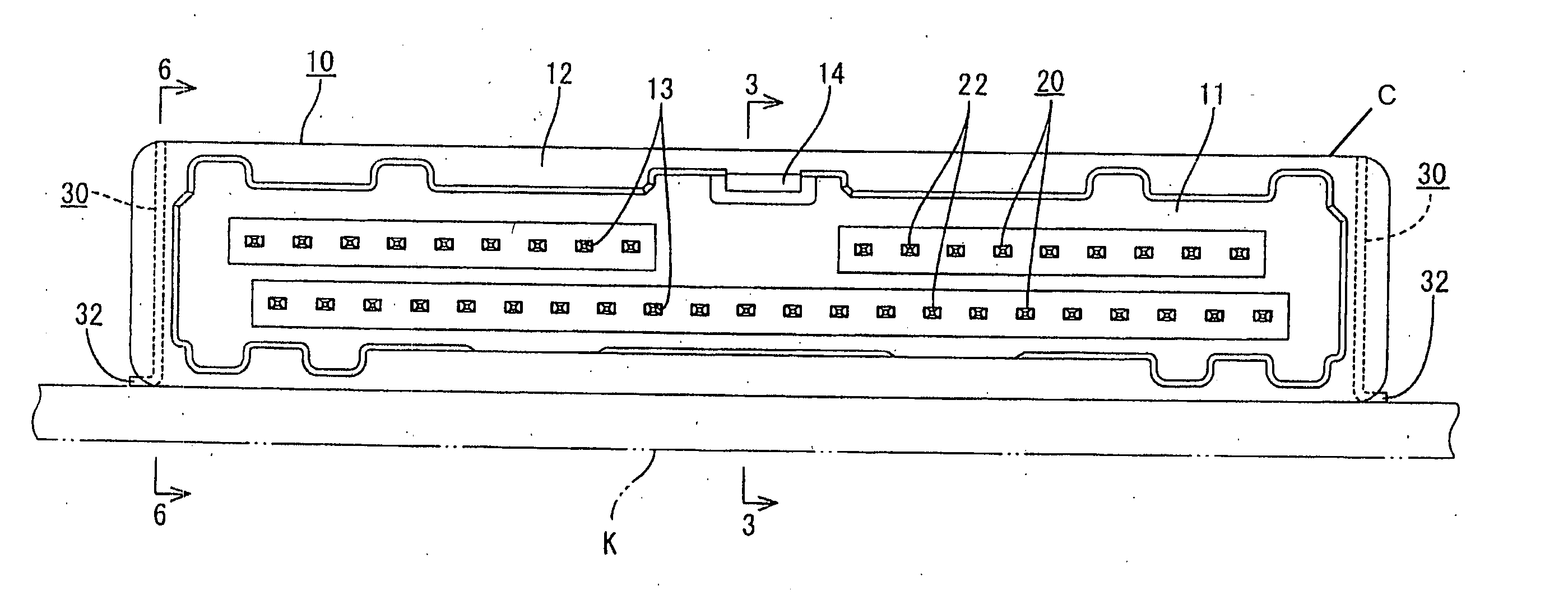
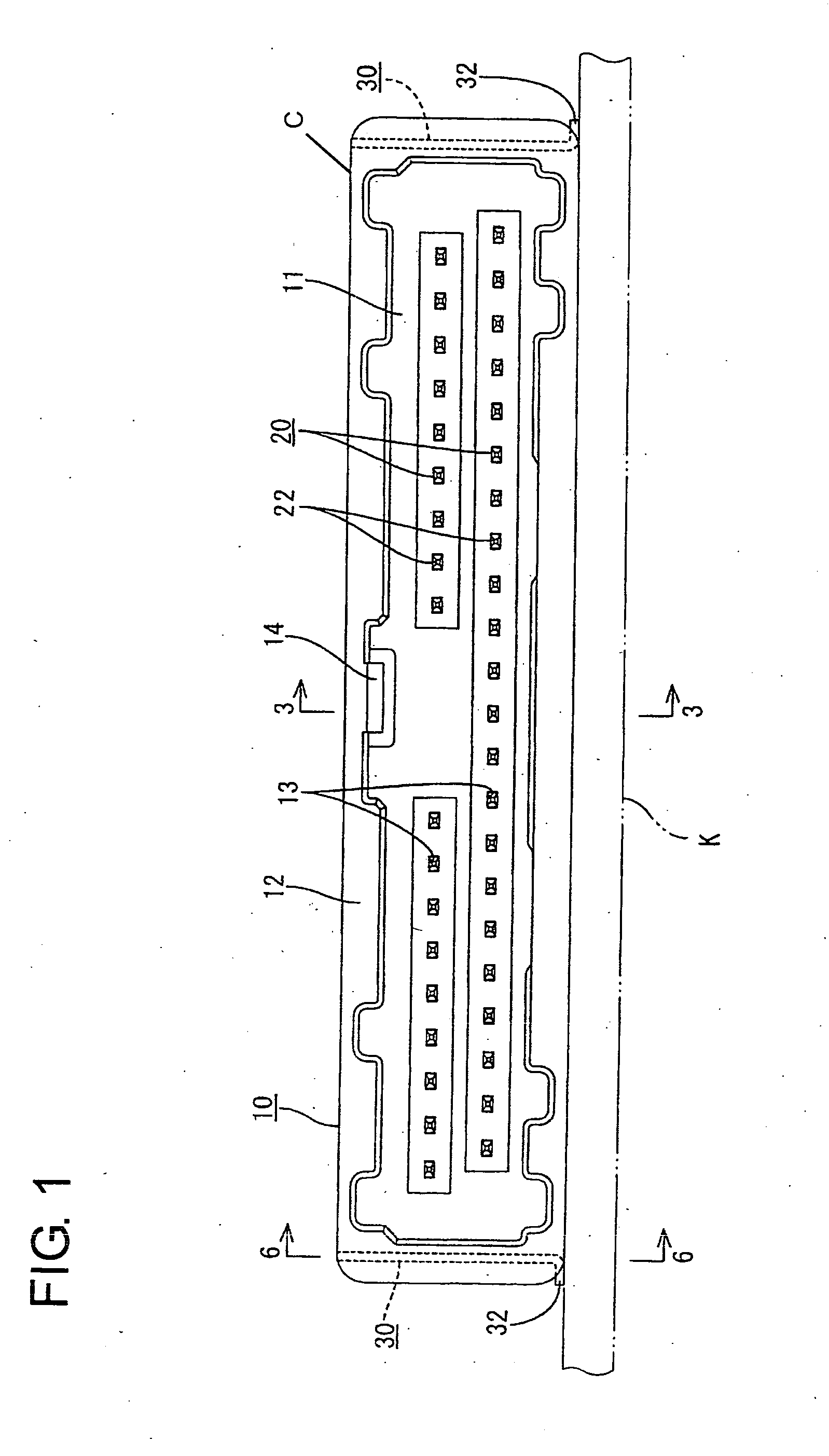
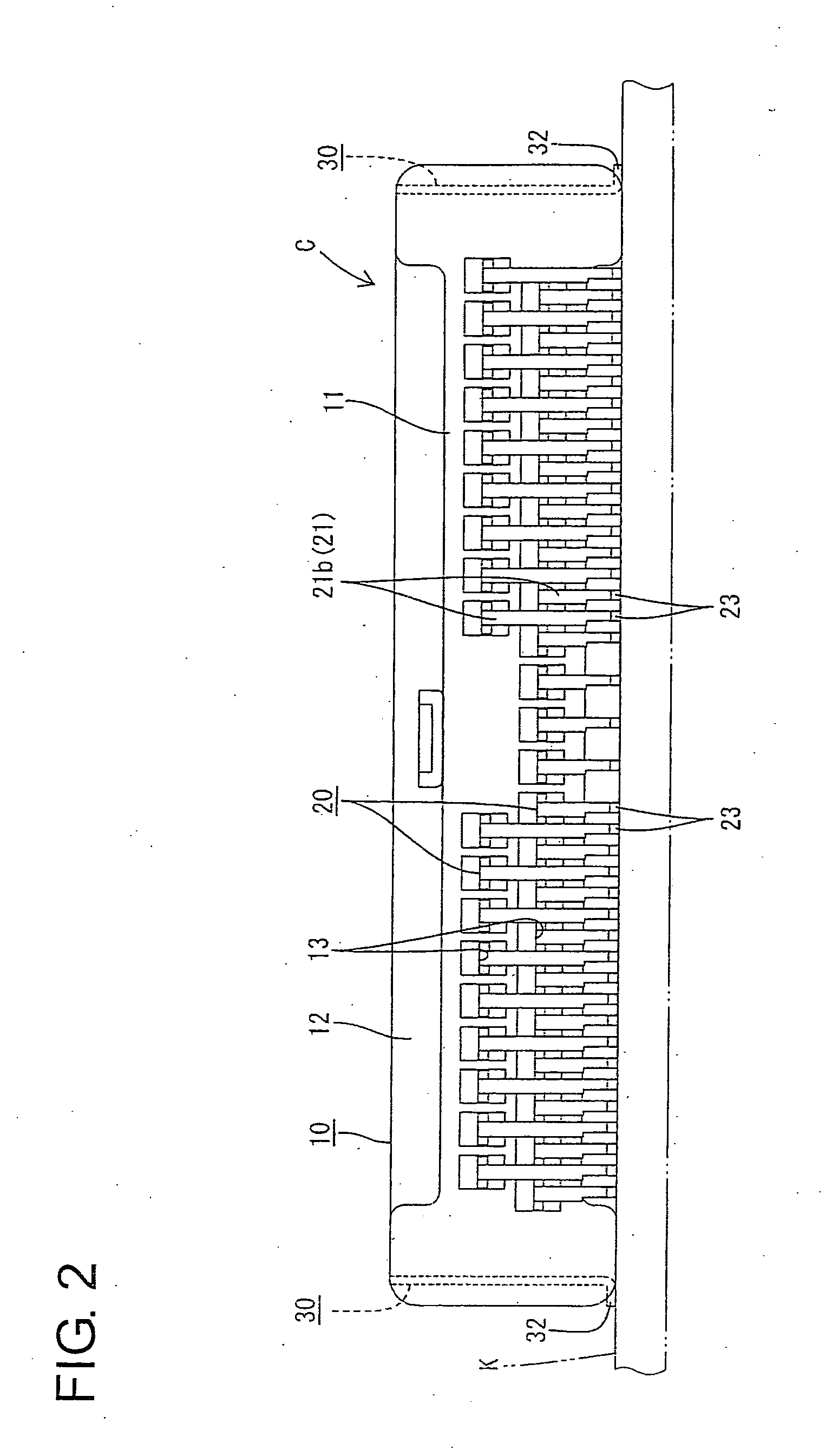
[0031] A circuit board connector C according to a first embodiment of the invention is described with reference to FIGS. 1 to 10. As shown in FIGS. 1 to 5, the circuit board connector C has a housing 10. Terminal fittings 20 and board fixing portions 30 are mountable in the housing 10. The housing 10 is fixed to a circuit board K by the board fixing portions 30 and is connectable with an unillustrated mating housing. In the following description, the end of the housing 10 that is to be connected with the mating housing (right side in FIG. 3) is referred to as the front, and reference is made to all the figures except FIGS. 4 and 11 concerning the vertical direction.

[0032] As shown in FIGS. 1 to 3, the housing 10 has a wide terminal holding portion 11 and a receptacle 12 that projects forward from a peripheral edge of the terminal holding portion 11. The terminal holding portion 11 is formed with a plurality of terminal insertion holes 13 for receiving the terminal fittings 20. The ...

Example

[0058] A second embodiment of the invention is described with reference to FIGS. 14 and 15. Elements of the second embodiment that are the same as or similar to the first embodiment are identified by the same reference numerals but are not described again.

[0059] The circuit board connector of the second embodiment has a board fixing portion 30A with a main plate 31, as shown in FIG. 14. A substantially rectangular bore 39 is formed in the middle portion 34 of the main plate 31 and defines arms 40 at the opposite sides of the middle portion 34. Each arm 40 is supported at its opposite ends and is resiliently deformable inward. A retaining projection 36 is formed on the outer side edge of each arm 40. The retaining projections 36 contact the groove edges as the board fixing portion 30A is inserted into the mount groove 15. Accordingly, the arms 40 deform resiliently inward and away from the groove edges of the narrow portion 19. Biting movements of the retaining projections 36 are al...


PUM


Abstract

A connector has a housing (10) is formed with mount grooves (15) into which board fixing portions (30) made of a metal plate are mountable. Each board fixing portion (30) has main plate (31) and a soldering leg (32) projecting laterally from a bottom portion (35) of the main plate (31). The board fixing portions (30) can be fixed to a circuit board (K) by placing the housing (10) on the circuit board (K) and soldering the soldering portions (32) of the board fixing portions (30) with the board fixing portions (30) mounted in the mount grooves (15).

Description

BACKGROUND OF THE INVENTION [0001] 1. Field of the Invention [0002] The invention relates to a circuit board connector. [0003] 2. Description of the Related Art [0004] Japanese Unexamined Patent Publication No. H05-326049 and FIG. 13 herein disclose a circuit board connector. With reference to FIG. 16, the connector has terminal fittings 1 accommodated in a housing 2 that is fixed to a circuit board 3. Board fixing portions 4 are formed integrally at the bottom ends of the opposite side surfaces of the housing 2 and bulge out sideways. Screw holes 5 are formed in the board fixing portions 4 and receive screws 6 for fixing the housing 2 to the circuit board 3. However, the screws 6 bite into the edges of the screw holes 5. As a result, the board fixing portions 4 must be sufficiently large to maintain strength, and hence, there is a tendency to enlarge the entire circuit board connector. [0005] Japanese Unexamined Patent Publication No. H06-325826 discloses another circuit board conn...

Claims


Application Information

Patent Timeline
IPC IPC(8): H01R13/46H01R4/02H01R12/50H01R12/71H01R13/41H01R43/02
CPCH01R4/028H01R12/707H01R43/0256H01R13/41H01R13/46
Inventor NAKANO, HIROSHIMAESOBA, HIROYOSHIOKAMURA, KENJI
Owner SUMITOMO WIRING SYST LTD
Why Eureka
Try Eureka