
Angled crosscut knife

Inactive Publication Date: 2006-02-23
EASTMAN KODAK CO
View PDF9 Cites 0 Cited by
  • Summary
  • Abstract
  • Description
  • Claims
  • Application Information

AI Technical Summary

Benefits of technology

[0007] Angling the knife allows the knife to easily and neatly cut through the web instead of merely ploughing through the web. Angling the knife to crosscut a photographic paper web produces a smooth cut without upsetting the edges of the web and while minimizing wasteful core impressions. The force required to cut the web is reduced by angling the knife producing a clean, effortless cut that minimizes the production of dirt and debris. Maximum razor knife life is obtained when the knife is angled which increases intervals between razor knife replacement thereby increasing productivity. A crosscut knife that is angled to the paper surface will use less force, produce a better quality cut and extend knife life while producing an angled cut edge to eliminate core impressions.

Problems solved by technology

This often results in a rough cut, with the cut edges upset due to the product being displaced by the trailing heel of the razor blade.
This upset results in core impressions on the first few wraps of product around the core.
Core impressions are a problem that may render the first few wraps of product adjacent the core unusable.
Additionally the rough cut results in more dirt and debris being produced.
Dirt and debris are problematic because they must be removed or else they will contaminate the photographic paper web reducing its quality or making it unusable.
Dirt and debris may also cause more rapid wear of the razor knife.
The forces required to urge the blade through the web also results in reduced knife life.

Method used


Image

  • Angled crosscut knife
  • Angled crosscut knife
  • Angled crosscut knife

Examples


Embodiment Construction

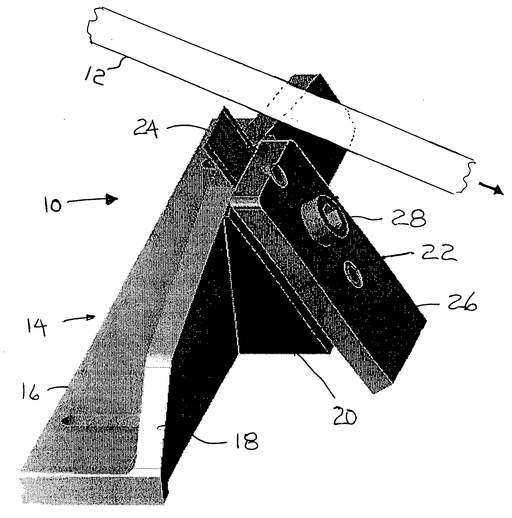
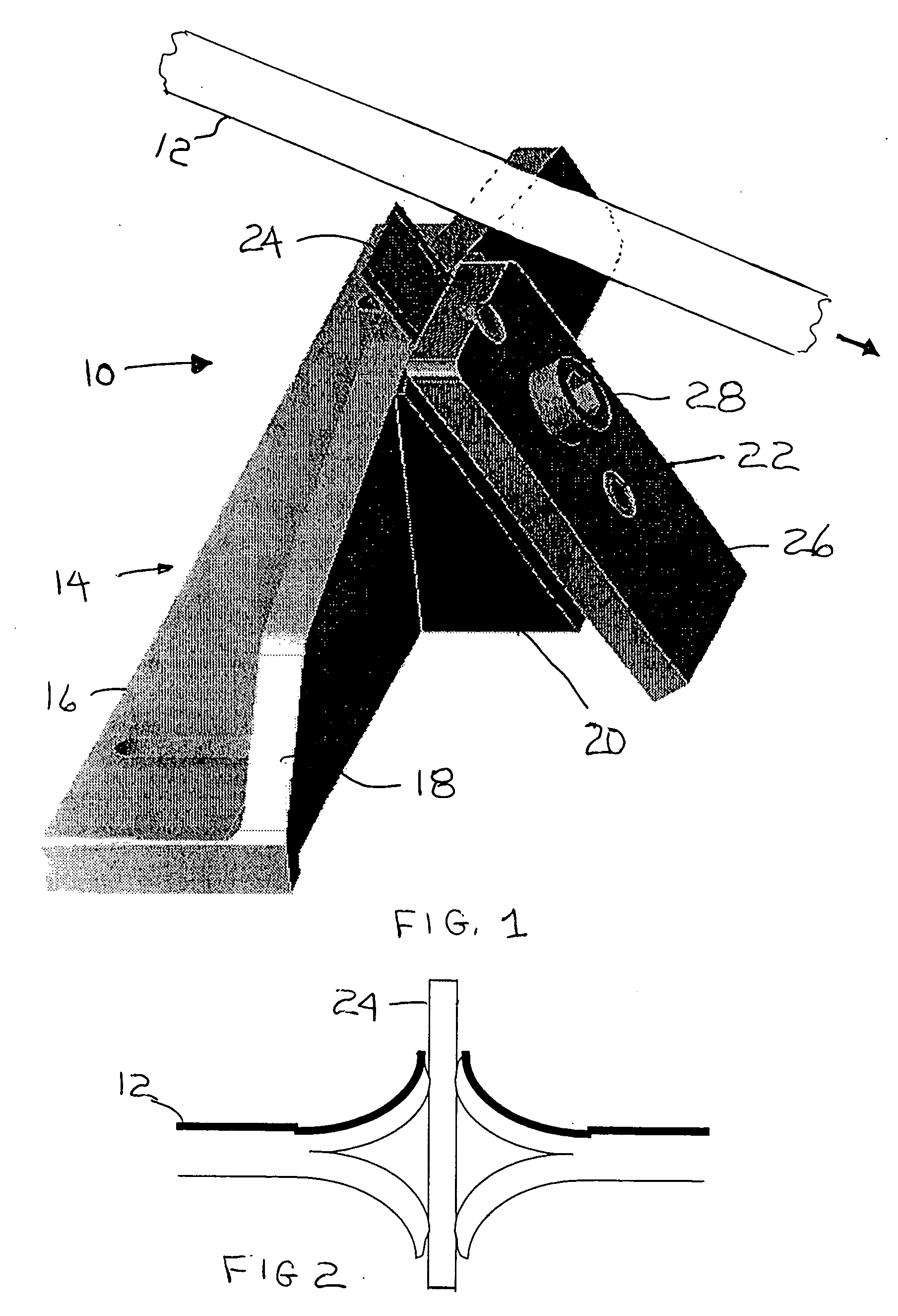
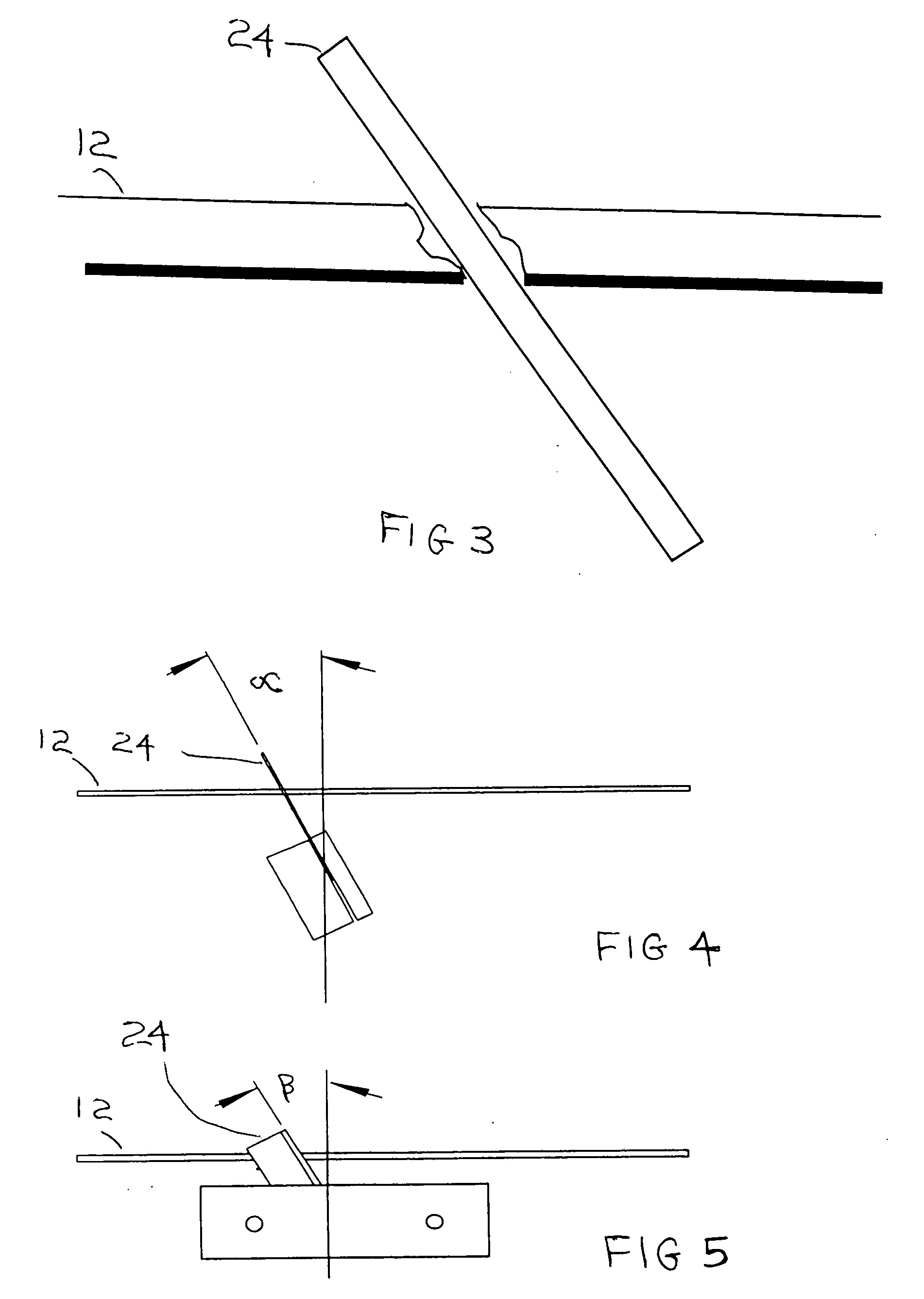
[0017] Referring to FIGS. 1-5, an apparatus 10 is configured for crosscutting a web 12 of material wherein the web 12 has front and rear opposed side edges and lies in an xy plane having horizontal and transverse boundaries. Such a plane would have x and y Cartesian coordinates with the web traveling in the x direction. The apparatus includes a mounting block 14 that is preferably movable in the y direction to intersect and cut the web. Mounting block 14 preferably has a base 16 and an upstanding flange 18. Base 16 lies parallel to the xy plane and flange 18 extends in the z direction.

[0018] A support member 20 has an inclined surface and is attached to flange 18 with the inclined surface facing outward away from flange 18. The inclined surface is tilted relative to the xy plane and thus to the web at a cant angle, α. It is preferred that support member 20 be removably mounted on flange 18 to facilitate tilting the inclined surface by removing one support member and replacing it wi...


PUM

PropertyMeasurementUnit
Angleaaaaaaaaaa
Angleaaaaaaaaaa
Angleaaaaaaaaaa

Abstract

An apparatus (10) and method for crosscutting a web (12) of material has employs a knife (24) that is angled relative to the surface of the web. Orienting the knife so that an upper portion of the cutting edge engages the web after a lower portion of the cutting edge engages the web facilitates cutting the web at a transverse cut angle (β) of about 20 degrees. Simultaneously orienting the knife so that the upper portion of the cutting edge engages the web at a different position along the side edge than the lower portion of the cutting edge facilitates cutting the web at a horizontal cant angle (α) in the range of about 10 degrees to about 50 degrees.

Description

FIELD OF THE INVENTION [0001] The invention relates generally to the field of cutting technology, and in particular to photographic paper cutting. More specifically, the invention relates to razor crosscutting of photographic paper. BACKGROUND OF THE INVENTION [0002] All paper slitters use some kind of cutting mechanism, usually a razor blade, to cut across the web when the correct length has been spooled on the core. After this crosscutting operation, the end of the spooled web is taped down and the finished roll is then bagged for the eventual customer. A web of photographic paper may consist of several layers of material. The current method of crosscutting photographic product webs is to use a razor blade angled perpendicular (90 degrees) to the web, and urge the blade through the web. This often results in a rough cut, with the cut edges upset due to the product being displaced by the trailing heel of the razor blade. This upset results in core impressions on the first few wraps...

Claims


Application Information

Patent Timeline
IPC IPC(8): B26D1/00
CPCB26D1/0006B26D2001/006B26D1/045Y10T83/04Y10T83/8773
Inventor SEYNA, JOHN J.SPENCER, ROBERT G.BARROS, GENIVAL D.
Owner EASTMAN KODAK CO
Learn More